Download
1 / 12
120 likes | 290 Views
SWANNANOA FIRE DEPARTMENT. 7 B asic Steps of Pump Operation. 7 B asic Steps of Pump Operation. 1. Proper Gear. 2. Tank to Pump. 3. Check what hose is used. 4. Open Proper valves. 5. Set Transfer Valve. 6. Throttle Up. 7. Set Relief Valve.

E N D
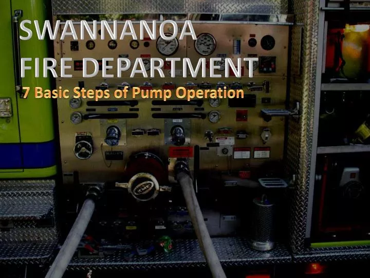
SWANNANOA FIRE DEPARTMENT 7 Basic Steps of Pump Operation
7 Basic Steps of Pump Operation 1. Proper Gear 2. Tank to Pump 3. Check what hose is used 4. Open Proper valves 5. Set Transfer Valve 6. Throttle Up 7. Set Relief Valve
1. Proper Gear 2. Tank to pump 3. Check hoselines 4. Open proper valve 5. Set transfer valve 6. Build pressure 7. Set relief valve 1. Proper Gear Every pump needs power to function. “Apparatus” typically use an engine/transmission (Mid-Ship) while “Portable pumps” may have a direct drive from engine to pump.
1. Proper Gear 2. Tank to pump 3. Check hoselines 4. Open proper valve 5. Set transfer valve 6. Build pressure 7. Set relief valve 1. Proper Gear What happens when you use the pump shifter and the transmission shifter? A B Pump shifter is in its middle pause position (Moving the pump shifter from “road” to “pump” should take NO LESS THAN 3-5 seconds) The rear drive axle is ready to gain power from the Engine/Transmission Note the orange circle in the drawings. This is the switch that once the VPS shift rod moves away, a signal is sent to activate the “OK to pump” green light on the dash or pump panel. D C Air pressure moves the VPS Shifter and shift fork forward, aligning the main gear with gears which will turn the impeller gears. The rear drive axle is “disconnected.” Once the transmission is shifted into drive, power from the Engine/Transmission are now directed to the pump
1. Proper Gear 2. Tank to pump 3. Check hoselines 4. Open proper valve 5. Set transfer valve 6. Build pressure 7. Set relief valve 2. Tank To Pump You must provide a source of water to enter the pump. On most initial attack operations, your supply will be the booster tank on the apparatus. Each apparatus will have a “Tank To Pump” valve handle located in a different area. Become familiar with each location. Note – If the valve is not opened or an external source of water does not enter, the spinning impeller will create heat and will eventually cause damage to the pump
1. Proper Gear 2. Tank to pump 3. Check hoselines4. Open proper valve 5. Set transfer valve 6. Build pressure 7. Set relief valve 3. Check what hose is off You must know what hoselines have been pulled to eventually open the proper valve in step 4. In some cases you may be the firefighter pulling a hoseline. Walk all the way around. Make sure the hose is ALL THE WAY out of its bed. If a kink or part of the hose remains in the bed it may become lodged and unusable once the line is pressurized Each discharge is labeled. You will have to match the color or wording with the same valve handle label at the pump panel
1. Proper Gear 2. Tank to pump 3. Check hoselines4. Open proper valve 5. Set transfer valve 6. Build pressure 7. Set relief valve 4. Open proper valve Pull the valve handle which supplies water to the hoseline which has been pulled off the truck Each discharge is labeled. You will have to match the color or wording with the same valve handle label at the pump panel
1. Proper Gear 2. Tank to pump 3. Check hoselines 4. Open proper valve 5. Set transfer valve 6. Build pressure 7. Set relief valve 5. Set Transfer Valve Only applies to a “2-Stage Pump” (Engine 61) The Transfer Valve sets the pump in “Pressure/Series” or “Volume/Parallel” The purpose of a transfer valve is efficiency of RPMs
1. Proper Gear 2. Tank to pump 3. Check hoselines 4. Open proper valve 5. Set transfer valve 6. Build pressure 7. Set relief valve 5. Set Transfer Valve Throttle below 50psi if you must switch during operations How do I know to use Pressure or Volume? The rule is based on “Half the rated capacity of the pump”
1. Proper Gear 2. Tank to pump 3. Check hoselines 4. Open proper valve 5. Set transfer valve 6. Build pressure 7. Set relief valve 6. Build Pressure You must know the correct pressure for the line/s in use. Increasing the throttle increases the engine speed causing the impeller to turn faster. Throttle up till your HIGHEST PSI LINE’S needed PSI is met on your “Master Discharge” gauge. Other lower PSI lines must be “gated down.” Using the Electronic Pressure Governor by pressing the “preset” then adjusting if needed or pressing the increase button OR Using the manual throttle cable on the pump panel
1. Proper Gear 2. Tank to pump 3. Check hoselines 4. Open proper valve 5. Set transfer valve 6. Build pressure 7. Set relief valve 7. Set relief valve The Relief Valve System is designed to re-route excess pressure and avoid causing damage to hoselines or pump parts. How it works
1. Proper Gear 2. Tank to pump 3. Check hoselines 4. Open proper valve 5. Set transfer valve 6. Build pressure 7. Set relief valve 7. Set relief valve Higher PSI than the setting pushes back Pilot Valve Spring and travels to Relief Valve Flowing water at 160psi Nozzle closed too quickly, PSI increases A B C D PSI higher than the pilot valve setting “pushes” the relief valve which moves, allowing higher PSI to flow by into the intake side of the pump or to the atmosphere (outside). The PSI reading will drop as this occurs. If the higher PSI was caused from closing a nozzle too quickly, the PSI will recover after the relief valve does its job If the higher PSI was caused from too many RPMs or “over throttling,” you will have to adjust the throttle setting or change the Pilot valve setting.