Download

1 / 13
200 likes | 565 Views
Composite Filament Winding Machine P09226. Detailed Design Review Christofer Brayton Shijo George Alex Sandy Tiago Santos Daniel Weimann. Background. Why composite tubing? High Strength Light Weight High creep and fatigue performance Chemical and corrosion resistance.

E N D
Composite Filament Winding Machine P09226 Detailed Design Review ChristoferBrayton Shijo George Alex Sandy Tiago Santos Daniel Weimann
Background Why composite tubing? High Strength Light Weight High creep and fatigue performance Chemical and corrosion resistance
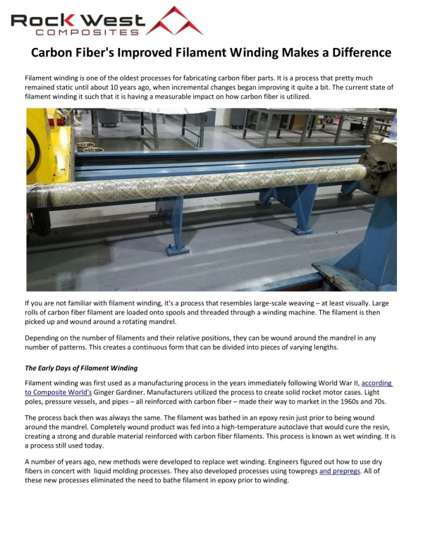
Filament Winding • The process by which a continuous strand of impregnated fibers is wound onto a mandrel with specific fibers’ orientation which is controlled by computer. • Once resin has cured, mandrel is removed
RIT First Generation Filament Winding Machine Capabilities • Produce tubes of limited dimensions • Simple to operate • Maintain tension every time • Limited range of orientation angles • Able to be expanded upon • Primary Goals • Learning Experience • New technology to RIT and students involved • Create simple but bulletproof machine
Relative Speeds • Relative Speeds control the angle at which fibers lay onto the mandrel θ is the fiber winding angle (°) r is the radius of the mandrel Nm is the speed of the mandrel [RPM] Vc is linear velocity of the feed eye P is the pitch of the rack NS is the pinion speed [RPM]
Motors - Mandrel Τ is the torque applied [N-m] F is the force applied [N] r is the radius on which the force is applied [m] m is the mass of applied load [kg] g is the acceleration of gravity [9.81 m/s2]
Motors – Feed Eye TL is the torque applied F is the force applied D is the diameter of the pinion η is the efficiency of the gear train (assumed to be .9) i is the Gear Ratio of the rack and pinion (1.5 in/rev)
Computer / User Interface B (+) B (+) RS-485 IN A (-) RS-485 IN A (-) IGND IGND SW2 SW3 Input 1 Input 1 SW6 SW11 Input 2 Input 2 CHB SW7 CHB SW12 ON/OFF +5V ON/OFF +5V SW8 V1 CHA SW13 V6 CHA Direction 5VDC Direction 5VDC INDEX SW9 INDEX SW14 Hard + GND Hard + GND SW10 SW15 0 Hard - 0 Hard - Output 1 Output 1 Feed Eye Mandrel VIN VIN V2 V7 12-24Vdc GND 12-24Vdc GND 23MDSI SERIES 23MDSI SERIES SW5 D1 0 R1 0 1k V4 SW MAG-SPST 3.3Vdc LED SW1 D2 R2 1k V5 SW MAG-SPST 3.3Vdc LED SW4 D3 R3 1k V3 SW MAG-SPST 3.3Vdc LED 0 Controls