Download
1 / 57
810 likes | 1.3k Views
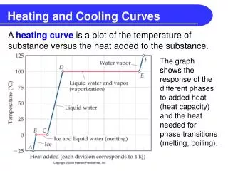
HEATING & COOLING EQUIPMENT. HEATING & COOLING EQUIPMENT. Heating Equipment Heat from combustion Natural Gas Propane Fuel Oil Coal Heat from Electricity Heating equipment is rated in BTUH. Combustion Heating Uses Furnaces or Boilers.

E N D
HEATING & COOLING EQUIPMENT Heating Equipment • Heat from combustion Natural Gas Propane Fuel Oil Coal • Heat from Electricity • Heating equipment is rated in BTUH
Combustion Heating Uses Furnaces or Boilers • Furnaces heat air and typically require fans and ductwork for distribution. • Boilers heat water and typically require pipes and pumps for distribution. They will also require some mechanism for transferring the heat from the water to the air. • Efficiency can reach 80% w/o heat recovery from exhaust gases & 95%w/heat recovery.
FURNACE or BOILER FURNACE BOILER
Combustion Heating Requires Basic Safety Precautions • Air for combustion (outside air). • Flue or chimney for exhaust gasses. • Controls for fuel & combustion. • Above ground supply lines to building for both safety and convenience of metering/shut-off. • Venting for any gas piping to prevent possible buildup of combustible gasses.
ELECTRIC HEATINGResistance Heating Advantages: • Low initial cost • Ease of installation • No exhaust necessary • Clean heat • No storage of fuel required • Instant heat
ELECTRIC HEATING Disadvantages: • Expensive to operate • Expensive to operate • Expensive to operate • The use of heat pumps can improve cost of operation. Heat pumps can make use of the heat that is still present in most air (in mild climates) & can also be used to cool.
HEAT PUMPS • Uses reversible refrigeration cycles w/ a four-way reversible valve (always removes heat from one source and rejects it to the other). This allows heat pumps to heat or cool. • Can be used w/furnaces or boilers. • Can be manufactured as “window units” or “packaged units”.
HYDRONIC HEATINGUses Water to Transfer Heat Basic Components: • Boiler to heat water • Piping to transfer the water (and heat) • Pump to move/push the water • Heat exchanger (radiator) to heat the air Will also need controls and safety devices.
CONVECTORS & RADIATORS Fin-Tube Convectors warm the air by conduction and convection. “Tubes w/fins”. Hot water (usually at 140°F or 180°F) flows through ½” or ¾” copper tubes w/ fins (usually aluminum). The large surface area of the fins heats the air; the hot air rises creating convection currents that brings cooler air to the convector.
CONVECTORS & RADIATORS Panel Radiators work in a similar manner to fin-tube convectors. Instead of tubes- flat, thin panels are filled by the flowing hot water. The hot panels function just like the hot fins to transfer heat and form convection currents. The main difference is the configuration and the resulting difference in space requirements. Fin-tube convectors typically run along the wall/floor junction. Baseboard radiators are similar to panel radiators in that they are hollow panels. W/o fins they produce about ½ the heat of fin-tube convectors.
PIPING & WATER FLOW Piping for convectors or radiators is basically the same. Water will flow from the boiler through the pump to the heat transfer device and back to the boiler. As the hot water flows through the heat exchanger it will lose heat (cool). If the water continues to flow through a series of exchangers it will continue to lose heat and each subsequent exchanger will be receiving cooler water and less heat to use. For this reason a simple one pipe system may not work well.
PIPING & WATER FLOW Reverse return piping sends the hot water back to the boiler from each exchanger through a separate pipe (the supply pipe only runs to the inflow side of the exchanger) until the last exchanger is reached. At this point the two pipes can merge so that only one pipe runs from the last exchanger back to the boiler. With this system hot water is fed to all the exchangers.
CONTROL VALVES, AIR VALVES, COMPRESSION TANKS & ACCESSORIES A variety of air ejectors, bleed valves, compression tanks and flow control valves are necessary to maintain proper flow and prevent damage to the system. Since water has a much higher capacity than air to hold and transfer heat, the water flow is low and the pump sizes are small, esp. for residential systems.
RADIANT HEATING Radiant heating can be electric or use hot water. Only the hot water system is covered in your text. Electric radiant heat is easy and inexpensive to install and easy to control. Since there are no moving parts it is very reliable. It also heats comfortably but like any resistance type electric heat it is expensive to operate.
RADIANT HEATINGUsing Hot Water Typically floors are used for the radiant surfaces. Hot air rises, we walk on & touch the floor surfaces most often and there will often be concrete construction for the floor. The piping for radiant heating is usually embedded in this concrete. Piping can be copper or plastic (PB or PEX). Serpentine loops form heating areas. Controls on the supply piping regulate each area.
RADIANT HEATINGUsing Hot Water Equipment: Piping- both supply/return and radiant. Boiler- to supply hot water (typically 110°F). Pump- to circulate the water . Expansion Tank and Air Ejector- to remove air and allow for changes in volume. Supply manifold and controls- to supply and control each heating loop.
RADIANT HEATINGUsing Hot Water Is efficient, quiet, unobtrusive, draft-free, clean and comfortable. It can also adjust heat levels independently in each area, zone or loop. Once properly installed it is typically low maintenance. Once the concrete loses heat and gets cold, it does take time to warm it back to comfortable temperatures.
FORCED AIR HEATING A fan is attached to the heat exchanger and increases the flow of heated air. This will provide a substantial increase in BTUH. In residential HVAC this may be called “central air” or “forced air”. In commercial construction this combination is “air handler” or “fan coil”. Air handlers work more like residential central air systems- they force the air through ducts. Fan coil units blow air directly from the unit into the room.
CAPACITY & HEAT OUTPUT The heat output is determined by the amount of water, GPM (gallons per minute) and the temperature drop (heat output is in BTUH). More water flow &/or more heat picked up will yield more heat. The amount of water flowing and the speed at which it flows determines the size of pipe and the size of the pump.
QUANTIFYING HEAT OUTPUT QHYDRONIC= (GPM) (500) (TD) QHYDRONIC= Heat output in BTUH GMP= Flow of water in gallons/minute TD= Temperature difference in oF Typically there is a 20oF temperature drop across a heat exchanger so a flow of 1GPM will yield about 10,000 BTUH.
ESTIMATING THE REQUIRED WATER FLOW IN GPM To estimate the water flow requirements for a typical building or room simply divide the heat loss in BTUH by 10,000 to get the GPM. The water velocity is usually held to less than 5 FPS. Table 16.5 shows approximate piping sizes for various BTUH requirements.
THE REFRIGERATION CYCLE A Refrigerant is used to pick up (absorb) heat and to release (throw off) heat. When refrigerants condense they release the heat that was captured when they evaporated. That is why we have evaporator coils (& fans) inside and condenser coils (& fans) outside. This allows for the heat indoors to be picked up and then released outdoors.
THE REFRIGERATION CYCLE In order to get the refrigerant to condense and to evaporate we need a compressor to increase pressure on the refrigerant and force it to condense and an expansion valve that allows the refrigerant to evaporate (expand). With these four components: evaporator coil, compressor, condenser coil and expansion valve we can have the refrigerant cycle through the equipment, absorb & release heat and as a result cool the indoors. Fans are used to increase the airflow and efficiency of the system.
AIR CONDITIONER Air conditioners use this refrigeration cycle to absorb heat from relatively cool inside air and release it to relatively warm outside air. The temperature difference between inside and outside air greatly effects an air conditioner’s efficiency. The greater the temperature difference the greater the amount of energy that is required and the less efficient the AC system will be.
HEAT AND REFRIGERANTS A typical refrigerant boils at 45oF and takes heat away from indoor air (75oF) and then is forced to condense at 125oF (by the compressor) and release heat to the outdoor air (95o). In effect the AC unit “moves” heat from the indoors to he outdoors. See AC diagrams:
SPLIT SYSTEM AC UNITS Split systems have the evaporator coils (& fans & ductwork) inside and the condenser coils (& fan & compressor) outside with refrigerant lines connecting them. This type of system saves space on the interior and allows for easier access to the condensing unit and compressor. The evaporator coils, fan and return air are all located close to each other on the interior for convenience & efficiency.
SEERSeasonal Energy Efficiency Ratio Air conditioner’s efficiency is measured by SEER. It is the number of BTU’s removed by 1 watt of electrical energy. Seer ratings range from 8 to greater than 14. An air conditioner’s efficiency also depends on load. Cooling load is the difference between heat source (indoor air) and heat sink (outdoor air) temperature. Larger condensing units will decrease condensing temperatures and lessen the load on the compressor reducing energy use.
COOLING TOWERS Water cooled refrigeration equipment can achieve higher SEER ratings (15-24) than air-cooled equipment because cooled water is used to lower condensing temperature and increase SEER. About 3GPM of water is required for each ton of cooling load. A ton of cooling load will remove 12,000 BTUH. Cooling towers act as evaporative coolers for the refrigerant from the condenser.
ABSORPTION COOLING Absorption cycle cooling uses heat instead of electricity to provide energy for the cooling process. A “chemical compressor” is used which includes an Absorber, a pump & a generator.
ABSORPTION COOLING This thermochemical process takes advantage of the fact that some chemicals tend to dissolve into other chemicals, a property chemists call "affinity." An absorption cycle uses two fluids: a refrigerant and an absorbent. In contrast to the compression that takes place in a conventional chiller, the refrigerant in an absorption chiller dissolves into an absorbent solution for which it has a high affinity. (Two common refrigerant/absorbent combinations are water and lithium bromide and ammonia and water.) An electric pump moves the absorbent solution into a generator section, where heat is applied to drive the refrigerant vapor out of the solution and into the evaporator. Substituting thermal energy for mechanical compression means that absorption chillers use much less electricity than mechanical compressor chillers. Absorption chillers are cost-effective when the thermal energy they consume is less expensive than the electricity that is displaced. Usually a supply of “waste” heat.
ABSORPTION COOLING Absorption-cycle cooling is typically only about ½ the efficiency of compressive-cycle cooling and the equipment is much larger; about 5 times the size. Absorption-cycle cooling is only energy efficient when there is a large supply of waste heat available from manufacturing processes, electrical energy generation or etc.
HEAT PUMP EFFICIENCY The heating efficiency of a heat pump is measured by COP (Coefficient Of Performance). Electrical resistance heating has a COP of 1. It delivers 3,400 BTU from each kilowatt (kW) of electrical energy used. Heat pumps have COP’s of 1 to more than 4. When a heat pump has a COP of 3 it delivers a total of 10,200 BTU; 3,400 BTU from the electrical input of 1 kW & 6,800 BTU from the latent heat in the air.