Download
1 / 31
340 likes | 533 Views
EELE 5490, Fall, 2009 Wireless Communications. Ali S. Afana Department of Electrical Engineering Class 4 Sep. 30 th , 2009. Fail of Iridium Satellite System. The system was originally to have 77 active satellites, and as such was named for the element iridium , which has atomic number 77.

E N D
EELE 5490, Fall, 2009Wireless Communications Ali S. Afana Department of Electrical Engineering Class 4 Sep. 30th, 2009
Fail of Iridium Satellite System • The system was originally to have 77 active satellites, and as such was named for the element iridium, which has atomic number 77. • Too few users per square miles, cost too much.
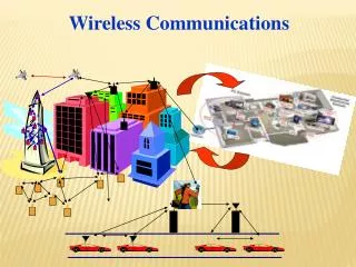
Cellular Concept • The limited capacity of the first mobile radio-telephone services was related to the spectrum used…not much sharing and a lot of bandwidth dedicated to a single call. • good coverage • interference: impossible to reuse the same frequency • The cellular concept addressed many of the shortcomings of the first mobile telephones • Frequency reuse • Wasted spectrum allocated to a single user • In 1968, Bell Labs proposed the cellular telephony concept to the FCC • It was approved and then the work began! • FCC allocated spectrum (took away TV UHF channels 70-83) in the 825-845 MHz and 870-890 MHz bands
Cellular Network Architecture Public Telephone network and Internet Mobile Switching Center Mobile Switching Center Wired network
Cellular Concept • developed by Bell Labs 1960’s-70’s • areas divided into cells • a system approach, no major technological changes • a few hundred meters in some cities, 10s km at country side • each served by base station with lower power transmitter • each gets portion of total number of channels • neighboring cells assigned different groups of channels, interference minimized • hexagon geometry cell shape
Frequency Reuse • Adjacent cells assigned different frequencies to avoid interference or crosstalk • Objective is to reuse frequency in nearby cells • 10 to 50 frequencies assigned to each cell • transmission power controlled to limit power at that frequency escaping to adjacent cells • the issue is to determine how many cells must intervene between two cells using the same frequency
Frequency Reuse • each cell allocated a group k channels • a cluster has N cells with unique and disjoint channel • groups, N typically 4, 7, 12 • total number of duplex channels S = kN • Cluster repeated M times in a system • Total number of channels that can be used (capacity) • C = MkN = MS • Smaller cells higher M higher C + Channel reuse higher capacity + Lower power requirements for mobiles • Additional base stations required • More frequent handoffs • Greater chance of ‘hot spots’
Effect of cluster size N • channels unique in same cluster, repeated over clusters • keep cell size same • large N : weaker interference, but lower capacity • small N: higher capacity, more interference need to maintain certain S/I level • frequency reuse factor: 1/N • each cell within a cluster assigned 1/N of the total available channels • In most of the current networks, frequency reuse factor is 1.
Design of cluster size • In order to connect without gaps between adjacent cells (to Tessellate) • N = i2 + ij + j2 where i and j are non-negative integers • Example i = 2, j = 1 • N = 22 + 2(1) + 12 = 4 + 2 + 1 = 7 • Next page example • move i cells along any chain or hexagon. • then turn 60 degrees counterclockwise and move j cells. • Example 3.1 in page 61
Example • N=19 • (i=3, j=2)
Channel Assignment Strategies • Fixed Channel Assignments • Each cell is allocated a predetermined set of voice channels. • If all the channels in that cell are occupied, the call is blocked, and the subscriber does not receive service. • Variation includes a borrowing strategy: a cell is allowed to borrow channels from a neighboring cell if all its own channels are occupied. • This is supervised by the Mobile Switch Center: Connects cells to wide area network; Manages call setup; Handles mobility
Channel Assignment Strategies • Dynamic Channel Assignments • Voice channels are not allocated to different cells permanently. • Each time a call request is made, the serving base station requests a channel from the MSC. • The switch then allocates a channel to the requested call based on a decision algorithm taking into account different factors: frequency re-use of candidate channel and cost factors. • Dynamic channel assignment is more complex (real time), but reduces likelihood of blocking
Handover/handoff • Reasons for handover • Moving out of range • Load balancing • Cell, BSC (base station controller), MSC (mobile switching center) • Handover scenarios • Intra-cell handover (e.g., change frequency due to narrowband interference) • Inter-cell, intra-BSC handover (e.g., movement across cells) • Inter-BSC, intra-MSC handover (e.g., movement across BSC) • Inter MSC handover (e.g., movement across MSC)
Four Types of Handoff 1 2 3 4 MS MS MS MS BTS BTS BTS BTS BSC BSC BSC MSC MSC
Handoffs • important task in any cellular radio system • must be performed successfully, infrequently, and imperceptible to users. • identify a new base station • channel allocation in new base station • high priority than initiation request (block new calls rather than drop existing calls)
Handoff • =handoff threshold - Minimum acceptable signal to maintain the call • too small: • Insufficient time to complete handoff before call is lost • More call losses • too large: • Too many handoffs • Burden for MSC
Styles of Handoff • Network Controlled Handoff (NCHO) • in first generation cellular system, each base station constantly monitors signal strength from mobiles in its cell • based on the measures, MSC decides if handoff necessary • mobile plays passive role in process • burden on MSC • Mobile Assisted Handoff (MAHO) • present in second generation systems • mobile measures received power from surrounding base stations and report to serving base station • handoff initiated when power received from a neighboring cell exceeds current value by a certain level or for a certain period of time • faster since measurements made by mobiles, MSC don’t need monitor signal strength • Mobile Controlled Handoff
Types of Handoff • Hard handoff - (break before make) • FDMA, TDMA • mobile has radio link with only one BS at anytime • old BS connection is terminated before new BS connection is made.
Types of Handoff • Soft handoff (make before break) • CDMA systems • mobile has simultaneous radio link with more than one BS at any time • new BS connection is made before old BS connection is broken • mobile unit remains in this state until one base station clearly predominates
Types of Handoff • Vertical handoff
Prioritizing handoff • Dropping a call is more annoying than line busy • Guard channel concept • Reserve some channels for handoffs • Waste of bandwidth • But can be dynamically predicted • Queuing of handoff requests • There is a gap between time for handoff and time to drop. • Better tradeoff between dropping call probability and network traffic. • Reduce the burden for handoff • Cell dragging • Umbrella cell
Interference and System Capacity • major limiting factor in performance of cellular radio systems • sources of interference: • other mobiles in same cell • a call in progress in a neighboring cell • other base stations operating in the same frequency band • Non-cellular system leaking energy into the cellular frequency band • effect of interference: • voice channel: cross talk • control channel: missed or blocked calls • two main types: • co-channel interference • adjacent channel interference
Co-Channel Interference • cells that use the same set of frequencies are called co-channel cells. • Interference between the cells is called co-channel interference. • Co-channel reuse ratio: Q = D/R=sqrt(3N) • R: radius of cell • D: distance between nearest co-channel cells • Small Q small cluster size N large capacity • large Q good transmission quality • tradeoff must be made in actual cellular design
Co-channel Reuse Ratio • SINR Power propagation factor 2-6
Cochannel Interference • SINR • Power: propagation factor 2-6 • Sun, nuclear bomb • Approximation • AMPS example • =4, S/I=18dB, N needs to be larger than 6.49. • Reuse factor 1/N small • Relations: cochannel interference, link quality, reuse factor • Example 3.2
Worst Case Interference • S/I ~ R-4 /[2(D-R)-4 + 2(D+R)-4 + 2D-4]
Adjacent Channel Interference • Interference resulting from signals where are adjacent in frequency to the desired signal. • Due to imperfect receiver filters that allow nearby frequencies to leak into pass band. • Can be minimized by careful filtering and assignments, and by keeping frequency separation between channel in a given cell as large as possible, the adjacent channel interference may be reduced considerably. • Example 3.3
Channel Planning and Power Control • Cell planning • Control channel 5% • Voice/data channel • f1/f2 cell planning • Breathing cell • Power Control • Open loop • Close loop • 800Hz in CDMA2000, 1500Hz in WCDMA