Download
1 / 41
410 likes | 564 Views
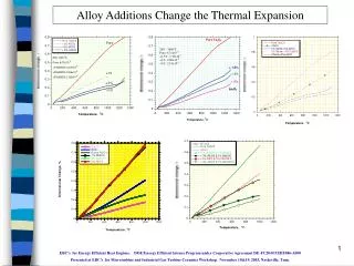
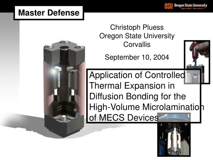
Master Defense. Christoph Pluess Oregon State University Corvallis September 10, 2004. Application of Controlled Thermal Expansion in Diffusion Bonding for the High-Volume Microlamination of MECS Devices. 1 of 36. Literature & Patent Review. Questions & Discussion.

E N D
Master Defense Christoph Pluess Oregon State University Corvallis September 10, 2004 Application of Controlled Thermal Expansion in Diffusion Bonding for the High-Volume Microlamination of MECS Devices
1 of 36 • Literature & Patent Review • Questions & Discussion • Theoretical Concept & Device Design • Introduction • Results & Conclusions • Experimental Approach • Finite Element Analysis (FEA) • Table of Contents 2004 Christoph Pluess
2 of 36 Bulk m-Fluidic Devices (MECS) • Introduction 2004 Christoph Pluess
3 of 36 t p T p OSU Device • Introduction Microlamination (Paul et al., 1999) • Patterning • Laser Micromachining • Chemical Etching • Registration • Pin Alignment • TEER (Thermal Enhanced Edge Registration) • Bonding • Diffusion Bonding • Diffusion Brazing 2004 Christoph Pluess
4 of 36 Production Capability: • Pump-down: 0.75-1h • Ramp-up: 0.75-1h • Bonding: 0.5-1h • Cool-down: 2-3h • Cycle Time: 4-6h • Introduction Why is this topic relevant? Example: Solid-State Diffusion Bonding within a Vacuum Hot Press Vacuum Hot Press, Nano/Micro Fabrication Facility 2004 Christoph Pluess
5 of 36 Device Size: • Large Substrate MECS Devices • Large Hot Press System ($) • Pressure Uniformity • Introduction Why is this topic relevant? Example: Solid-State Diffusion Bonding within a Vacuum Hot Press Vacuum Hot Press, Nano/Micro Fabrication Facility 2004 Christoph Pluess
6 of 36 Conveyor Furnace “Sequoia”, MRL Industries • DCTE Fixture • DCTE, free source of pressure • low expanding frame • high expanding inner parts • Continouous Furnace System • Similar to microelectronics industry • high-volume microlamination • Introduction Using thermal expansion? Possible solution? 2004 Christoph Pluess
7 of 36 • Introduction DCTE Bonding Fixture • Is this a plausible approach for microlamination? • Can a particular fixture design provide control over: • Pressure magnitude? • Pressure timing? • Pressure sensitivity? 2004 Christoph Pluess
8 of 36 • Literature & Patent Review Is this idea unique? • Use of thermal expansion for pressure application first stated by PNNL in 1999 • Most papers/publications try to minimize effects of thermal expansion • Patents where thermal expansion is used to apply pressure/force: • Clamping ring for wafers US 5,460,703 (1995) • Belt press using DCTE US 6,228,200 (2001) 2004 Christoph Pluess
9 of 36 2003, McHerron, IBM • Literature & Patent Review Is this idea unique? Patent Application Publication US 2003/0221777 A1 McHerron et al. International Business Machines Corp. (IBM) Method and Apparatus for Application of Pressure to a Workpiece by Thermal Expansion 2004 Christoph Pluess
10 of 36 • Is this a plausible approach for microlamination? • Can a particular fixture design provide control over: • Pressure magnitude? • Pressure timing? • Pressure sensitivity? • Literature & Patent Review IBM Patent Application • Lamination of multilayer thin film structures (MLTF) • Use for continuous production and high throughput • Reduction of capital expenditures for lamination of MLTF 2004 Christoph Pluess
11 of 36 Theoretical Study and Model Development • Theoretical Model Gap closure function: Resulting strain in z-direction: Resulting pressure in z-direction : 2004 Christoph Pluess
12 of 36 • initial gap variations of 1mm pressure change 1.6 MPa • assumed accuracy with feeler gage 5mm 8.0 MPa Geometrical Sensitivity: 1.6 MPa/mm • temperature fluctuations of 5°C pressure change 4.7 MPa Thermal Sensitivity: 0.94 MPa/°C • Theoretical Model Sensitivity Analysis Applying reasonable material properties and sizes: • Lowering thermal sensitivity increases geometrical sensitivity • Lowering geometrical sensitivity increases thermal sensitivity 2004 Christoph Pluess
13 of 36 Pressure Timing: Initial gap adjustment Low expanding fixture frame Pressure Magnitude: Preloading and force storage with spring elements High expanding engagement block Pressure Sensitivity: Spring constant • Fixture Concept 2004 Christoph Pluess
14 of 36 • Fixture Design Fixture Frame: Initial gap setting Inner Parts: Load Cell Bonding Platens Inconel Disc Springs • Designed to fit in hot press ( 3”) • Max. service temperature 800°C • Bonding area 25x25mm (2 stations) Engagement Block Cu Laminae 2004 Christoph Pluess
15 of 36 Purpose of FE-Model • Validation of developed fixture design • Proof of feasibility • Theoretical assessment of pressure magnitude, timing and sensitivity • Fixture Model (FEM) 2004 Christoph Pluess
16 of 36 • Fixture Model (FEM) Expansion Behavior (in z-direction) • gap closure function: 2004 Christoph Pluess
17 of 36 • Fixture Model (FEM) p-Timing, p-Magnitude, p-Sensitivity • 150 times less sensitive than simple fixture model (0.94MPa/°C) 2004 Christoph Pluess
18 of 36 • Fixture Simulation 2004 Christoph Pluess
19 of 36 • Experimental DCTE-Fixture Prototype 2004 Christoph Pluess
20 of 36 • Experimental Experimental Overview Validation Experiments Test Article Orientation 2004 Christoph Pluess
21 of 36 • Experimental Experimental Overview Validation Experiments Test Article Orientation Load Cell Validation • Theoretical: 10’960 N/mm • Practical: 11’215 N/mm (+2.3%) 2004 Christoph Pluess
22 of 36 before: 3.0 3.5 4.0 4.5 5.0 5.5 6.0 MPa after: 3.0 3.5 4.0 4.5 5.0 5.5 6.0 MPa • Experimental Experimental Overview Validation Experiments Test Article Orientation • Fuji Pressure Sensitive Film Load Cell Validation p-Uniformity Bonding Platens 2004 Christoph Pluess
23 of 36 • Experimental Experimental Overview Validation Experiments DT Test Article Orientation 0°C Load Cell Validation 300°C p-Uniformity Bonding Platens 400°C p-Timing during Lamination 600°C 800°C • Experimental • Theoretical (FEM) 2004 Christoph Pluess
24 of 36 • Experimental Experimental Overview Validation Experiments • At low temperature (180°C): Test Article Orientation g0=0mm g0=30mm g0=50mm g0=70mm Load Cell Validation p-Uniformity Bonding Platens • T-limit of Fuji film 180°C • No contact situation with g0 > 63mm based on theoretical model • Experimental validation of DCTE- Fixture at low temperature! • Uniform pressure distribution p-Timing during Lamination p-Timing of DCTE-Fixture 2004 Christoph Pluess
25 of 36 • Experimental • T-profile optimization by connecting TC directly to temperature control unit: Experimental Overview Validation Experiments Test Article Orientation Load Cell Validation p-Uniformity Bonding Platens • Furnace cool down optimization with helium cooling: p-Timing during Lamination p-Timing of DCTE-Fixture TC Measurements 2004 Christoph Pluess
26 of 36 DCTE-Fixture Hot Press vs. • Experimental Experimental Overview Validation Experiments Final Experiment Test Article Orientation Fin warpage (timing) Load Cell Validation Void fraction (p-magnitude) p-Uniformity Bonding Platens p-Timing during Lamination p-Timing of DCTE-Fixture TC Measurements 2004 Christoph Pluess
27 of 36 • Experimental DOE Final Experiment • 24 full-factorial design with 1 replicate (32 runs) • Mode: Hot Press / Fixture • Pressure: 3 MPa / 6 MPa • Temperature: 500°C / 800°C • Time: 30’ / 60’ • 2 samples each run for a total of 64 test samples 32 32 • ANOVA on fin warpage (128 measurements) • ANOVA on void fraction (160 measurements) 2004 Christoph Pluess
28 of 36 • Results ANOVA Fin Warpage • No statistical significant difference observed (p-value 0.92) • Average fin warpage hot press: 3.99 mm 0.44 mm • Average fin warpage DCTE-fixture: 4.02 mm 0.44 mm 2004 Christoph Pluess
29 of 36 • Results Void Fraction Inspection • Metallographic preparation of the 16 samples • 10 inspection locations for each DB set (160 measurements) • Voids were marked on a • transparency at 384X • Calculation of void fractions • (reference length 250 mm) 2004 Christoph Pluess
30 of 36 • Results Metallographic Pictures Bond Lines (Void Shrinkage) Hot Press DCTE-Fixture 500°C 3 MPa 60 min 78.8% 70.5% 800°C 3 MPa 60 min 15.8% 23.2% 800°C 6 MPa 60 min 8.0% 9.6% 2004 Christoph Pluess
31 of 36 • Results ANOVA & Table of Means for Void Fraction • Statistical significant difference observed • Since T & t are equal, variation is due to pressure applied 2004 Christoph Pluess
32 of 36 • Results ANOVA for Void Fraction (Interactions) • Less significant difference at low pressures • (frame stiffness maintained) • Less significant differences at high temperatures • (void fraction less pressure sensitive at high temp.) 2004 Christoph Pluess
33 of 36 • Results Comments • Timing of pressure within the DCTE-fixture did not show • any problems • Although void fractions showed a difference, bond quality is comparable • Source of p-variation due to the use of high expanding stainless steel bolts (potential loss of preload) • Level of pressure was dampened due to spring • implementation in frame (loss of rigidity) 2004 Christoph Pluess
34 of 36 • Conclusions • Is this a plausible approach for microlamination? • Can a particular fixture design provide control over: • Pressure magnitude? • Pressure timing? • Pressure sensitivity? yes ( yes) yes yes 2004 Christoph Pluess
35 of 36 • Future Research • DCTE-Fixture design for large substrates • Validation of large substrate fixture design with FEM: • Structural, p-uniformity • Thermal, T-gradients • Process optimization for continuous production line • Experimental investigation of large substrate bonding 2004 Christoph Pluess
36 of 36 • Questions & Discussion Thanks for your attention! M.S. Defense Presentation Christoph Pluess September 10th 2004 Oregon State University Corvallis USA Special thanks to: Major Professor Dr. Brian K. Paul Committee Members: Dr. Sundar V. Atre Dr. Kevin M. Drost Dr. Timothy C. Kennedy Dr. Zhaohui Wu Special thanks to: Steven Etringer 2004 Christoph Pluess
Additional Slides 2004 Christoph Pluess
Experimental First DCTE-Prototype • 7 MPa at 800°C • 5 Cu-layers bonded: 02/20/2004 • 1st successful DCTE-bond 2004 Christoph Pluess
Fixture Model (FEM) FE-Model Features (ANSYS) • ¼ model • 6655 elements (17’000 nodes) • LINK10 prevented use of contact elements • One solid structure (SOLID95) • Spring constant, initial gap, preload of load cell defined over real constants • Input of bonding parameters over Scalar Parameter Menu • Automatic load step definition and execution with APDL-macro 2004 Christoph Pluess
FE-Model Settings Real Constant Settings 2004 Christoph Pluess