Download
1 / 22
220 likes | 221 Views
Automatic Transmit Power Control Canadian Context. V. Sahay Aviat Networks. What Is ATPC?. Automatic Transmit Power Control is a mechanism built into a microwave radio so that the output power of the transmitter is adjusted in response to fading on the path

E N D
Automatic Transmit Power Control Canadian Context V. Sahay Aviat Networks
What Is ATPC? • Automatic Transmit Power Control is a mechanism built into a microwave radio so that the output power of the transmitter is adjusted in response to fading on the path • ATPC also provides additional protection from critical traffic disconnects due to ducting and temporary antenna feeder system problems • Fading may be caused by multipath propagation or by precipitation, dominated by one or the other depending on the frequency band • ATPC has been widely used in many countries for over 40 years, early on to eliminate receiver overload, now to reduce interference levels in frequency congested areas
Advantages of ATPC • Intrinsically, ATPC may extend the life of the transmitter electronic components • Reduces power consumption in some cases • Increases system gain with smaller T-R separations due to reduced intra-system (PA pedestal) noise. • Reduces interference to other systems during up-fades. • Eliminates receiver overloads, thus allowing increased fade margins for better performance and availability • Facilitates frequency coordination
Role in Coordination - Multipath • Radios using ATPC normally operate with reduced transmit power which will increase significantly only during deep fades. • In frequency bands below 12 GHz, the main fading mechanism is multipath propagation in most areas • Fading on adjacent paths is non-correlative and hence very short term power increases in one path will occur likely while the other path has lots of fade margin. • Coordination based on short-term power increases will result in closer spacing between adjacent paths than coordination based on maximum interfering power.
Role in Coordination - Rain In bands where rain is the predominant fading mechanism, correlation of fading between nearby paths is not clear cut, but the following is considered: • Rain cells can last for several minutes unlike multipath • Rain cells which can be several miles in diameter will attenuate both the wanted and interference signals if on-path, and thus has no affect on interference • Rain cells occurring only in the wanted path is typically uncorrelated with adjacent path fades, plus antenna discrimination greatly reduces interference path levels, thus interference to the victim receiver is unlikely • Hence, interference analysis based on less than maximum power should be evaluated on case by case basis.
Coordinated Transmit Power ATPC systems have three transmit power levels: • Pn = Nominal Power which occurs in clear air • Pm = Maximum Power • Pc = Coordinated Power used for frequency coordination purposes Under ATPC rules the power is allowed to exceed Pc only for pre-specified periods In diversity hops, the transmitter ATPC step or ramping is triggered only with both far-end receivers simultaneously faded
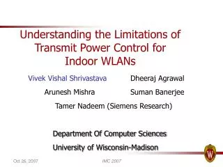
Power above Coordinated Permitted time Transmit (annual) Power (dB) Percentage Seconds of time per year 0.0 0.50 157,500 1.0 0.33 103,950 2.0 0.22 69,300 3.0 0.15 47,250 4.0 0.10 31,500 5.0 0.07 22,050 6.0 0.047 14,805 7.0 0.032 10,080 8.0 0.021 6,615 9.0 0.014 4,410 10.0 0.010 3,150 TIA Bulletin TSB-10-F Rules (2)
Determination of Coordination Power • Step 1: Select a candidate Pc. • Step 2: For each possible ATPC power level, P determine the excess above Pc = ΔP • Step 3: From ATPC “transfer function” determine the duration of the fade, ΔF, which would result in P • Step 4: Determine the percentage of time that ΔF is exceeded using local “fading statistics” • Step 5: Compare this percentage of time with the TSB-10-F criteria for ΔP and repeat as necessary.
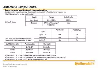
Transmit power (dBm) 2 0 3 0 0 4 0 5 0 10 Fade Depth ( dB) ATPC Transfer Function
Special Cases • Because shallow fade statistics are pathlength dependent, a 10 dB fade must occur before the coordination power is exceeded • In case of a step function, only the percentage of time related to the threshold level at which ATPC is triggered needs to be checked • In the case of a ramping function, only the % of time P>Pc and P>Pm need to be checked
ATPC Ramp Function (1) 25 Pm ΔP=10 Pc 19 RSL (dBm) 14 -43 Pn Tx Power, RSL (dBm) ΔFm=27 ΔFc=17 Fade RSL -52 dBm -55 Receiver Outage -65
ATPC Ramp Function (2) • Power increases dB for dB once ATPC is activated • In example, 12 dB fade is needed to activate ATPC and • 17 dB to cause power to exceed Pc=19 dBm • ΔP = 0; ΔF = 17; P(ΔF ) = .1326% < .5% • 27 dB fade to exceed Pm = 29 dBm • ΔP = 10; ΔF = 27; P(ΔF ) = .0133% > .01%
ΔFading ATPC Step Function 30 ΔP = x Pc Transmit Power (dBm) -42 20 RSL (dBm) -57 Δ F = 25 -67
Step Function (2) • Power increases in a single step of up to 10 dB once ATPC is activated • In this example, the ATPC trigger is 10 dB above the BER outage threshold -77 dBm • Nominal power of 20 dBm is sufficient to provide an RSL of -42 dBm. • Coordinated power is selected to be at the nominal power level of X dBm.
Step Function (3) • At 10 dB/decade, the 25 dB RSL reduction implies a 25 dB fade • Prob(ΔF=25 ) = .0086% • For a Pmax = 30 dBm, ΔP = 30-X dB • Criteria for X= 20, ΔP = 10 • Since .0086% < .01%, meets criterion
Calculation of Conformity • Use of Local Propagation statistics to determine % of time fading exceeds ΔF • Vigants Method (requires c factor which is combination of radio climatic zone and terrain) • ITU-R 530-13 Method (requires similar factors) • Results not exactly same though close • Vigants method used in US widely
Implementation Guidelines - NSMA • ATPC trigger minimum 10 dB Fade • Coordinated Power not more than 10 dB below maximum power; used for coordination • Power higher than Coordinated power limited for %time as given in TSB 10F • Max power on for more than 5 minutes should set off alarms • Rain Paths coordinate with maximum power • For interference into Paths with ATPC, assume max wanted power for C/I calculations
Implementation Guidelines - NSMA • ATPC trigger minimum 10 dB Fade • Coordinated Power not more than 10 dB below maximum power; used for coordination • Power higher than Coordinated Power limited by calculation for %time as given in TIA Bulletin TSB-10-F • Maximum Power on for more than 5 minutes should set off alarms to initiate possible maintenance action. If alarm caused by fading due to ducting and sensitive traffic is used then it may be necessary to continue. • Rain-affected paths coordinate with Coordinated Power if possible or with Maximum Power • During coordination, ATPC paths assume Maximum Power (maximum fade margin) for C/I and performance and availability calculations
Regulatory Implications • Encourage use of ATPC in congested areas through licensing policy • Use of Vigants model in border areas