Download
1 / 6
60 likes | 139 Views
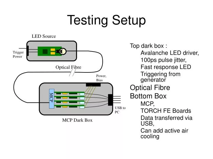
Testing Setup. Top dark box : Avalanche LED driver, 100ps pulse jitter, Fast response LED Triggering from generator Optical Fibre Bottom Box MCP, TORCH FE Boards Data transferred via USB, Can add active air cooling. Firmware / Software. FPGA firmware provides:

E N D
Testing Setup • Top dark box : • Avalanche LED driver, • 100ps pulse jitter, • Fast response LED • Triggering from generator • Optical Fibre • Bottom Box • MCP, • TORCH FE Boards • Data transferred via USB, • Can add active air cooling
Firmware / Software • FPGA firmware provides: • Raw data output for debug, • Zero suppressed data output, • Slow control HPTDC (via JTAG). • Software: • Event display, • Histogram, • LED triggering for testing, • Temperature reading.
Power Consumption Estimation • 16-CH Testing board • 4 board per MCP • Power per MCP: 13w • (alternative: 8-ch NINO x2 216mW)
TORCH Front End Board • 4 FE Boards per 8x8 MCP, • 16-channel per board, 2x8-ch NINO, 2x8-ch HPTDC, one small FPGA, and USB controller • USB socket, 5V DC power, analogue bias/ power for NINOs
Power Consumption Estimation • 256-CH detector board • 4 board per MCP • Total power: 200W • It’s a monster! Possibility of new HPTDC?