Download
1 / 18
180 likes | 258 Views
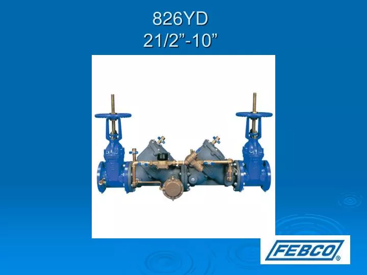
826YD 21/2”-10”. Modification Overview. Production of the 826YD began in 1989 and is current. The 826YD uses a ¾” 825Y as the bypass assembly. Check Cover Removal. Cover is o-ring sealed. 21/2-3” cover is spring loaded. * Hold cover firmly while removing bolts.

E N D
Modification Overview • Production of the 826YD began in 1989 and is current. • The 826YD uses a ¾” 825Y as the bypass assembly.
Check Cover Removal • Cover is o-ring sealed. • 21/2-3” cover is spring loaded. * Hold cover firmly while removing bolts. • 4-10” Loosen bolts ½”. Spring load is now released from the cover and retained by the check assembly. * Verify spring load before removing all the bolts.
Check Valve Removal • Center stem guided check assembly. • 21/2-3” spring, stem, and disc holder are free once cover is removed. • 4-10” disc & spring subassembly. • Slide subassembly straight out of seat and body.
Check Seat Removal • Seats are o-ring sealed and bolted into the body. • Remove bolts and pull seat straight out of body. • Inspect the plastic guide bushing in center of seat.
Check Disc Replacement • Unthread the nut from the stem and remove disc retainer.
Check Valve Reassembly Notes • Reassemble in reverse order. • Apply lubricant to o-rings. • 21/2-3” Models- inspect and clean the plastic guide in the check cover.
RV Cover Removal • Remove external sensing line. • RV cover is sealed by the diaphragm. • No spring load on cover. • Remove outer diaphragm.
RV Module Removal • Module is o-ring sealed. • Pull module straight out of body. * Grasp the module (button) with one hand and insert fingers (other hand) into RV port and apply force to the seat disc. * Do not twist module.
RV Seat Removal • RV seat is mounted between the RV housing and the RV adapter. • Remove the 4 bolts on the adapter and remove housing. • Seat is o-ring sealed. • Pull the seat straight out.
Disassemble RV Module • Place the module on a flat surface with lower guide facing up. • Hold the main stem with one hand and unscrew the lower guide.
Disassemble RV Module • With lower guide removed, place the module upside down on a clean surface. • Remove center of protective sticker (Save). • Hold the button firmly and loosen screw. * Button is spring loaded.
Disassemble RV Module • Remove main stem and unthread the retainer. • Remove slip ring and inner diaphragm.
Inner Diaphragm Replacement • Position the bead of the inner diaphragm into the groove of the upper guide. • Place slip ring over the diaphragm. • Thread retainer ring onto upper guide – (hand tight).
Main Stem Replacement • Push the inner diaphragm back through the upper guide assembly. • Insert main stem inside diaphragm. • The screw hole on diaphragm and main stem should be lined up.
Spring / Button Replacement • Place the spring over the upper guide assembly. • Place button on spring and hold down firmly. • Replace button screw. • Reposition center label piece.
RV Disc Replacement • Replace the RV disc in main stem. • Replace the disc washer and lower stem guide. • Replace and lubricate o-ring on main guide
RV Reassembly Notes • Reassemble RV in reverse order. • Push the RV module straight into body. * Do not twist. • Replace outer diaphragm with fabric side against button. • Work the rolled edge into the space between the module and body.