Download
1 / 20
210 likes | 578 Views
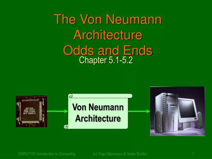
The Von Neumann Architecture Odds and Ends. Chapter 5.1-5.2. Von Neumann Architecture. Designing Computers. All computers more or less based on the same basic design, the Von Neumann Architecture !. The Von Neumann Architecture.

E N D
The Von Neumann ArchitectureOdds and Ends Chapter 5.1-5.2 Von Neumann Architecture (c) Yngvi Bjornsson & Vadim Bulitko
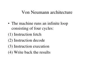
Designing Computers • All computers more or less based on the same basic design, the Von Neumann Architecture! (c) Yngvi Bjornsson & Vadim Bulitko
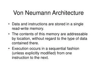
The Von Neumann Architecture • Model for designing and building computers, based on the following three characteristics: • The computer consists of four main sub-systems: • Memory • ALU (Arithmetic/Logic Unit) • Control Unit • Input/Output System (I/O) • Program is stored in memory during execution. • Program instructions are executed sequentially. (c) Yngvi Bjornsson & Vadim Bulitko
Communicate with • "outside world", e.g. • Screen • Keyboard • Storage devices • ... Store data and program Execute program Do arithmetic/logic operationsrequested by program The Von Neumann Architecture Bus Memory Processor (CPU) Input-Output Control Unit ALU (c) Yngvi Bjornsson & Vadim Bulitko
Structure of the Memory Subsystem • Fetch(address) • Load address into MAR. • Decode the address in MAR. • Copy the content of memory cell with specified address into MDR. • Store(address, value) • Load the address into MAR. • Load the value into MDR. • Decode the address in MAR • Copy the content of MDR into memory cell with the specified address. MAR MDR F/S Memory decoder circuit Fetch/Store controller ... (c) Yngvi Bjornsson & Vadim Bulitko
Implementation of the Memory Subsystem (c) Yngvi Bjornsson & Vadim Bulitko
CACHE - Modern addition • High-speed memory, integrated on the CPU • Ca. 10 times faster than RAM • Relatively small (128-256K) • Stores data most recently used • Principle of Locality • When CPU needs data: • First looks in the cache, only if not there, then fetch from RAM. • If cache full, new data overwrites older entries in cache. Memory Processor (CPU) I/O Cache Control Unit ALU (c) Yngvi Bjornsson & Vadim Bulitko
I/O Subsystem: Hard-Drives • Uses magnetic surfaces to store the data. • Each surface has many circular tracks. • Each track consists of many sectors. • The surfaces rotate at a high speed • Typically ~7000 rev/min • The read/write arm moves: • back and forth to locate a track (c) Yngvi Bjornsson & Vadim Bulitko
Hard-Drive (c) Yngvi Bjornsson & Vadim Bulitko
Disk Access Time • The time it takes to read/write data to a disk, consists of: • Seek time • The time it takes to position the read/write head over correct track (depends on arm movement speed). • Latency • The time waiting for the beginning of the desired sector to get under the read/write head (depends on rotation speed) • Transfer time • The time needed for the sector to pass under the read/write head (depends on rotation speed) • Disk Access Time = Seek time + Latency + Transfer time • Measure worst, best, and average case. (Example: p. 189) (c) Yngvi Bjornsson & Vadim Bulitko
GT EQ LT Structure of the ALU R0 • Registers: • Very fast local memory cells, that store operands of operations and intermediate results. • CCR (condition code register), a special purpose register that stores the result of <, = , > operations • ALU circuitry: • Contains an array of circuits to do mathematical/logic operations. • Bus: • Data path interconnecting the registers to the ALU circuitry. R1 R2 Rn ALU circuitry (c) Yngvi Bjornsson & Vadim Bulitko
ALU Circuitry Implementation of the ALU Every circuit produces a result but only the desired one is selected (c) Yngvi Bjornsson & Vadim Bulitko
Structure of the Control Unit • PC (Program Counter): • stores the address of next instruction to fetch • IR (Instruction Register): • stores the instruction fetched from memory • Instruction Decoder: • Decodes instruction and activates necessary circuitry PC IR +1 Instruction Decoder (c) Yngvi Bjornsson & Vadim Bulitko
Machine Language Instructions • A machine language instruction consists of: • Operation code, telling which operation to perform • Address field(s), telling the memory addresses of the values on which the operation works. • Example: ADD X, Y (Add content of memory locations X and Y, and store back in memory location Y). • Assume: opcode for ADD is 9, and addresses X=99, Y=100 Opcode (8 bits) Address 1 (16 bits) Address 2 (16 bits) 00001001 0000000001100011 0000000001100100 (c) Yngvi Bjornsson & Vadim Bulitko
Implementation of the Control Unit (c) Yngvi Bjornsson & Vadim Bulitko
von Neumann Architecture (c) Yngvi Bjornsson & Vadim Bulitko
How does this all work together? • Program Execution: • PC is set to the address where the first program instruction is stored in memory. • Repeat until HALT instruction or fatal error Fetch instruction Decode instruction Execute instruction End of loop (c) Yngvi Bjornsson & Vadim Bulitko
Program Execution (cont.) • Fetch phase • PC --> MAR (put address in PC into MAR) • Fetch signal (signal memory to fetch value into MDR) • MDR --> IR (move value to Instruction Register) • PC + 1 --> PC (Increase address in program counter) • Decode Phase • IR -> Instruction decoder (decode instruction in IR) • Instruction decoder will then generate the signals to activate the circuitry to carry out the instruction (c) Yngvi Bjornsson & Vadim Bulitko
Program Execution (cont.) • Execute Phase • Differs from one instruction to the next. • Example: • LOAD X (load value in addr. X into register) • IR_address -> MAR • Fetch signal • MDR --> R • ADD X • left as an exercise (c) Yngvi Bjornsson & Vadim Bulitko
Instruction Set for Our Von Neumann Machine (c) Yngvi Bjornsson & Vadim Bulitko