Download
1 / 24
400 likes | 511 Views
ADVANCED 8-PIN LOAD-SHARE CONTROLLER UCC39002 UCC29002 UCC29002/1. What is Load Share?. What is Load Share? Provides equal distribution of the load current among parallel voltage-stabilized power supplies Why parallel supplies? High current/low voltage applications

E N D
ADVANCED 8-PIN LOAD-SHARE CONTROLLERUCC39002UCC29002UCC29002/1
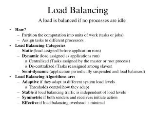
What is Load Share? • What is Load Share? • Provides equal distribution of the load current among parallel voltage-stabilized power supplies • Why parallel supplies? • High current/low voltage applications • Redundancy for enhanced reliability • Hot Swap capability • Distributed heat removal • Space and cost
Output impedance of power modules < 1mW When connected in parallel, the supply with the highest Vout will supply the majority of the output current. Because the output R is so low, it doesn’t take a large difference in Vout for this to result in large current differences. Current-limit mode increased stress = decreased reliability Why would you need a Controller?
Basic concept of load-share controller: supply a voltage feedback loop Iout of each module is accurately measured then compared to a current share bus Vout is adjusted so each module delivers an equal amount of output current The Concept
Modules must have True remote sense capability or an output voltage adjustment terminal Pre-biased load capability Temporarily disable SR FET so as not to sink current which would discharge Cout during SS resulting in voltage glitching, neg transients, start up oscillations Must source but not sink current Decoupling diode (not ORing FET) Without the diode sourcing modules will pump current into the sinking module. SR acts as booster to pump energy from the common output DC bus to the primary of the module sinking current. Need one load share controller per module The Modules
Fully compliant with Intel SSI Specs Server System Infrastructure Power Supply and Chassis Physical dimensions, wattage ratings, electromechanical interface parameters Single connection between parallel modules Scalable load share voltage independent of Rsense High Accuracy, better than 1% at full load High-side or low-side current sense capability Hot-swap, Enable, Disconnect-at-Standby BiCMOS MSOP-8 package Improvements over the UC3902
Means for generating and distributing current sharing information between modules Must be insensitive to noise pickup 15 kHz pole LS voltage determined by the Master Forward biases the diode at the LS driver output VLS compared to the other module’s CSA output at the Gm error amp Drives the ADJ amplifier which adjusts the modules output voltage LS Bus
UCC39002, UCC29002, UCC29002/1 • Start Up Logic • LS driver disabled • ADJ amp sinks max current • Normal operation resumes when measured current >80%LS • Start up logic masked out in the UCC29002/1
Original Design (UCC29002 and UCC39002) At start up, LS driver is disabled and ADJ amp is forced to sink MAX current Starts in known state Module forced full on to engage in sharing asap Output of module adjusted high At 80% of LS, ADJ amp reverts to normal What and Why
/1 Prompted by Cisco Output oscillating at start up “The difference is the inverter coming from the hysteretic comparator off the CS amplifier is disconnected (it's the one in the center of the block diagram). Since it's disconnected, we ground out the NFET on the positive input of the error amplifier. The inverter also was going into an AND gate at the bottom of the diagram that feeds into an NFET that can pull up the Adjust amplifier's positive input to 3V. That signal going to the AND gate is now tied to ground, which disables the NFET being able to pull the + input on the Adjust amp to 3V.” What and Why
Module output voltages railed at start-up Some triggered OVP and latched ADJ sink current much higher than 6mA (18mA reported) at the instant of start up…it did settle out immediately Some customers do not want their modules to be set at the max during start up Oscillations also triggered during large and fast line or load transients Indication of Problem
UCC39002/UCC29002/UCC290021 • LS protection
UCC39002/UCC29002/UCC290021 • Iout too low
UCC39002/UCC29002/UCC290021 • Enable and Disconnect
Layout Quiet IC GND: use quiet no-current Sense- trace for GND pin; not the high current load return Use Kelvin connections for the module sense lines Do not Add Capacitor on LS: Bus receiver already has an internal 15kHz filter, any stray capacitance may result in stability issues VDD cap not just for bypass but compensation for active clamp Optimized for 0.1uF to 1uF with minimal inductance CSA not unity gain stable: requires gain of 3X or more Measure load share accuracy across a shunt so measurement does not interfere with the amplifier outputs Close the loop at least 1 decade before fco of module Loop is slow and will not function during transients: may take 100ms to catch up Over Current Protection Starting into full system load could trigger hiccup mode Outputs That Sink and Source Current Start Up Logic Outputs less than 1V: need to reference GND to neg bias to keep ADJ from Saturating No Remote Sense: can use trim Outputs Greater Than 15V Omitting Step #1 Other Common Mistakes
Module’s Internal Sense Resistor • What happens when the Module Manufacturer has an internal low value resistor between +Vout and +Sense? • RADJ will be in parallel • Most recent data sheet and MathCAD file have incorporated this
EVM: HPA027A Board has three controllers on it Reference designators left unpopulated so the Customer can customize for their specific application MathCAD File in the Tools and Software Section of the Product Folder Step by step user-interactive The Bode plot of the module must be re-created by the user Load Share Resources