Download
1 / 56
560 likes | 563 Views
Mu2e: A Muon to Electron Conversion Experiment at FERMILAB. James Miller, Boston University. FNAL, November 10, 2006. The Process: m - -> e - Conversion. m - are stopped in a target and form hydrogenic atoms (FNAL-Mu2e: muonic aluminum)

E N D
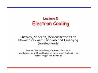
Mu2e: A Muon to Electron Conversion Experiment at FERMILAB James Miller, Boston University FNAL, November 10, 2006
The Process: m-->e- Conversion • m- are stopped in a target and form hydrogenic atoms (FNAL-Mu2e: muonic aluminum) • Main processes for muon in atomic orbit:: neutrino-less m->e conversion, capture, decay • Measure ratio: (conversion rate) / (ordinary capture rate): • Re={Rate(-+A(N,Z) e-+A(N,Z)} / {Rate(-+A(N,Z) +X} L=+1,Le=0 L=0,Le=+1 • The electron is mono-energetic, Ee~105 MeV: most background is from muon decay electrons which are dominantly below 55 MeV • Lifetime of muonic Al is 0.88 ms • Current limit, from SINDRUM II experiment at PSI: R< 6.1x10⁻¹³ (on Ti) • Mu2e goal at FNAL: R< 1x10-16 • SINDRUM II was limited by • Available muon fluxes, <108/s • Prompt background, mainly from radiative pion capture in the Al target: p- +A -> X + g, Eg up to ~139 MeV, g can convert to electron with Ee~105 MeV Must behighlysuppressed: used beam + electron coincidences and degrader • Mu2e: use an intense pulsed beam (ala MECO); no beam counters or degrader • Inject intense bunches of narrow (<~100-200 ns), low p (<70 MeV/c) muon beams. Stop them in an aluminum target • Begin data collection ~700 ns after injection; prompts (mainly pions) have subsided • Collect data from 700 ns to ~ 1.5 ms (matches muonic Al lifetime of 0.88 ms) • Inject pulses every ~1.5 ms (total of 1010-1011 muons per second) • Suppress protons by factor of 109 between injections (‘Extinction’) to avoid prompts
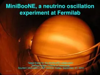
History of Lepton Flavor Violation Searches 1 - N e-N + e++ e+ e+ e- 10-2 10-4 10-6 10-8 10-10 10-12 K0+e-K+++e- MEG Goal(m->eg) SINDRUMII 10-14 (m->e) FNAL m->e Goal 10-16 19401950 1960 1970 1980 1990 2000 2010
SINDRUM II A eA Limit Experience of SINDRUM II carried over to the design of beam and experimental apparatus SINDRUM II has thebest limit on this process Prompt Background Cosmic RayBackground Re<6.1x10⁻¹³ (in Ti) Magnet: B=1.2 T,1.3 m dia., 1.5 m long Expected Signal Muon Decay in Orbit Experimental signature is 104 MeV eoriginating in a thin Ti stopping target
Candidate Approach for an FNAL-Based Experiment: MECO Apparatus 1 T 1 T Muon Beam 2 T Superconducting Solenoids Calorimeter Straw Tracker Stopping Target Foils Proton Beam Detector Solenoid 10 m long x 0.95 m rad 2.5 T 5 T Transport Solenoid 13 m long x 0.25 m rad Pion Production Target Production Solenoid 4m long x 0.75 m rad
Magnetic Spectrometer for Conversion Electron Momentum Measurement Sample event- this onefirst travels upstream, is reflected by B gradient back toward detector Electron starts upstream, reflects in field gradient Shown: Longitudinal straw option Straws: 2.6 m length 5mm dia., 25 m wall thickness to minimize multiple scattering – 2800 total • tracker will intercept between 2 and 3 helical turns
Probability Rate (proton flux=1x10¹³ Hz) Events (run time= 4x10⁷ seconds, total p’s =4x10²⁰) Prob. Muon stopped in target per proton 0.0025 0.25x10¹¹ Hz 1x10¹⁸ Prob. capture (Al target) 0.60 1.5x10¹⁰ Hz 6x10¹⁷ Fraction of captures in detector time window 0.45 (> 700 ns ) 0.7x10¹⁰ Hz 3x10¹⁷ Track fitting and selection criteria 0.19 1.2x10⁹Hz 5x10¹⁶ Detected events for Re=10-16 10-16 1.2x10⁻⁷Hz 5 single-event sensitivity 2x10-17 Estimated background 0.45 FNAL-Mu2ebeam rates and sensitivity
Some History: The BNL-Based Experiment (MECO) • MECO: one of two experiments on the cancelled NSF- RSVP project (along with KOPIO, ) • Cost of MECO by itself was projected at $56 M for the muon solenoidal beam line magnets + $24 M for the detector system • Project was not funded mainly because the cost to configure and run the AGS, plus to build both experiments and then decommission was deemed to be too large due cost escalations- however MECO was not the source of most of the cost escalation. • Advanced conceptual magnet design was produced • Initial prototypes and concepts of detector systems were produced • MECO successfully passed through several physics and technical reviews
Mu2e Personnel • Significant fraction of ex-MECO collaboration • Group at FNAL which has spent spare time investigating how to supply the proton beam and to site at FNAL • A number of other physicists attended the Sep 15-16 meeting of interested parties at FNAL- total of ~50 attendees
Summary of Beam Requirements • Pulsed ~4-8 GeV proton beam • Width < 100-200 ns (Narrower is better, but not critical) • Repetition Period ~1.5 ms • Proton Intensity > 1013 Hz • Integrated proton flux=4x10²⁰ • Beam Extinction < 10-9
e W What Will Observation of -N e-N Teach Us? Discovery of -N e-Nor a similar charged lepton flavor violating (LFV) process will be unambiguous evidence for physics beyond the Standard Model. • For non-degenerate neutrino masses, n oscillations can occur. Discovery of neutrino oscillations required changing the Standard Model to include massive . • Charged LFV processes occur through intermediate states with n mixing. Small n mass differences and mixing angles expected rate is well below what is experimentally accessible. • Charged LFV processes occurin nearly all scenarios for physics beyond the SM, in many scenarios at a level that Mu2e will detect. • Effective mass reach of sensitivesearches is enormous: well beyondthat accessible with direct searches. One example of new physics, with leptoquarks lmd led
Sensitivity to Different Muon Conversion Mechanisms Supersymmetry Compositeness Predictions at 10-15 Second Higgs doublet Heavy Neutrinos Heavy Z’, Anomalous Z coupling Leptoquarks After W. Marciano
The MECO Beam and Detector (T)5 3 1 A number of design parameters are based on MELC proposal of 1980’s B (Tesla) vs. s along beam 10 m x 0.95 m rad m 0 10 20 30 13 m x 0.25 m rad 4m x 0.75 m rad
Outline • Brief descriptions of the - e- process and the current and proposed experimental limits • Preliminary look: Could it be done at FNAL? Start with MECO-like design? Results of recent meeting at FNAL…. • General design issues of the Mu2e experiment- following the previously proposed but un-funded BNL-MECO approach?
Muon to electron conversion • Measure rate of the lepton flavor violating (LFV) reaction: neutrinoless muonto electron conversion in the field of a nucleus, relative to the ordinary muon capture rate on a nucleus. • Goal: Mu2e (and MECO) Re< 10-16 on Al which is ~ 4000x better than the current limit from SINDRUM II: Re<6.1x10⁻¹³ on Ti Reis the ratio of rates measured in a muonic atom, Re={Rate(-+A(N,Z) e-+A(N,Z)} / {Rate(-+A(N,Z) +A’(N+1,Z-1)} L=+1,Le=0 L=0,Le=+1 The conversion electron has a monochromaticenergy which is well above most of the background flux.
Why m-A e-A ? Some Options to m-A e-A : • t LFV may be significantly stronger in some models, but experimental challenges are large, solutions are difficult: super B-factory for t->mg? • Kaon LFV no stronger in most models, experimental improvements are difficult. • m->eg decay (MEG) is more sensitive in photon mediated processes by x200-x400, but is not more sensitive for other types of LFV reactions. (MEG at10-13 is 3x less sensitive than FNAL m->e proposal even for photon-mediated LFV, and 1000x less sensitive for other modes). May be experimentally limited by backgrounds to 10-13to 10-14. • What could change before next m-A e-A? • MEG (PSI) may see m->eg at 10-13 (or at ‘super MEG’ upgrade limitof 10-14) • LHC may discover new particles (e.g. supersymmetry). m-A e-A will be needed to help sort things out, e.g. the flavor structure.
Why m-A->e-A at FNAL? • Tens of man-years are invested in a MECO design which is applicable to FNAL. • Physics case was reviewed repeatedly w/excellent outcome • Well developed conceptual design exists, magnets have preliminary engineering design, some detector prototype work has been completed • Technical case reviewed repeatedly w/excellent outcome • An advanced cost estimate was produced • The continuing neutrino program at FNAL provides facilities and an accelerator operation well-matched to m->e experimental needs. • A working group has been established to understand how the appropriate proton beam can be supplied at FNAL.
Muonic Atom Formation and Nuclear Capture • A rapid process: low energy - (KE< 30 MeV) stop in target A(N,Z), undergo atomic cascade arriving primarily in atomic 1s state • Bohr radii n/mZ)EmZ2/n2 : 200x smaller radius and 200x more binding energy than atomic electron 1s muon is well inside electron orbits muon formshydrogen-like atom • Hydrogenic Radial wavefunction: Rnl(r) rl Z3/2 for small r. Prob. of overlap between nucleus and muon wavefunction is proportional to r2lZ3, which for small r and low to medium Z, is large only whenl=0. • Ordinary Muon Capture Rate -A(N,Z) A’(N’,Z’) a bn cp: <a>~2, <b>~2, <c>~0.1 Fundamental process: p -> n Proportional to: (# protons)x(nuclear overlap) ~ Z4 .Capture ~ decay rate for Z=12 • Muon Conversion Rate- + A(N,Z) A(N,Z) + e Coherent process proportional to (# nucleons)2x(nuclear overlap) ~Z5 Re high Z preferred. But… - Nucleus
->e Conversion Rates vs. Z Nucleus Re(Z) / Re(Al) Bound lifetime Atomic Bind. Energy(1s) Conversion Electron Energy Prob decay >700 ns Al(13,27) 1.0 .88 s 0.47 MeV 104.97 MeV 0.45 Ti(22,~48) 1.7 .328 s 1.36 MeV 104.18 MeV 0.16 Au(79,~197) ~0.8-1.5 .0726 s 10.08 MeV 95.56 MeV negligible Plot of Re(Z)/Re(Z=13) For various photon couplings (Rates Normalized to Z=13, Aluminum) Kitano, et al.PRD 66, 096002 (2002) Aluminum is nominal choice for MECO
Probability Rate (proton flux=1-2x10¹³ Hz) Events (run time= 2-4x10⁷ seconds, total p’s =4x10²⁰) Prob. Muon stopped in target per proton 0.0025 0.25-0.5x10¹¹ Hz 1x10¹⁸ Prob. capture (Al target) 0.60 1.5-3x10¹⁰ Hz 6x10¹⁷ Fraction of captures in detector time window 0.45 (> 700 ns ) 0.7-1.4x10¹⁰ Hz 3x10¹⁷ Track fitting and selection criteria 0.19 1.2-2.5x10⁹ Hz 5x10¹⁶ Detected events for Re=10-16 10-16 1.2-2.5x10⁻⁷ Hz 5 single-event sensitivity 2x10-17 Estimated background 0.45 Old BNL- MECO andnewFNAL-Mu2ebeam rates and sensitivity
Classes of background • Prompt: due to beam particles which interact almost immediately when they enter the detector region, producing electrons in the signal region, 100 MeVE106 MeV, or low energy background. • Examples: • Pions: Radiative pion capture, -+A(N,Z)+X. Very high suppression of pions is required, since it is a potentially major background. • Beam electrons: incident on the target and scattering into the detector region. Need to suppress ewith E>100 MeV • In-flight muon decays. Keep p<75 MeV/c to keep Ee<100 MeV • Antiproton annihilations along beam line or near target- (none in SINDRUM II, potential problem at 8 GeV at for MECO at AGS and at FNAL) • Delayed: due to beam particles which take > few hundred nanoseconds before they produce signals in the detectors. • Examples: • Electrons from muon decay in orbit (DIO) • Protons, neutrons, gammas from muon capture • Photons from radiative muon capture • Cosmic Rays- Back/Signal proportional to (run time)/(beam intensity)
Decay of a Muon Bound in Atomic Orbit (- + N(A,Z))bound -> N(A,Z) + e + e + (DIO) • Decay of a muon bound in an atom is slightly different from ordinary free muon decay… • Nucleus absorbs momentum -> neutrinos can carry zero momentum, with electron recoiling off of the nucleus electron can take almost all of the muon rest energy, and the endpoint energy is the sameasa potential conversion electron, but fortunately the probability is very low. Ee(max)= (mc2NuclearRecoilEnergy AtomicBindingEnergy) For Z=13 (Al), Atomic BE=0.529 MeV, Recoil energy=0.208 MeV Ee(max)=104.96 MeV Free muon decay, endpoint =52.8 MeV Muon decay in Al 1s bound state, endpoint=104.96 MeV 104.96 MeV
Major Potential Background: Decay of a Muon Bound in Atomic Orbit (DIO, Continued) ( + N(A,Z))bound -> N(A,Z) + e + e + • Rate near the maximum energy falls very rapidly. Near endpoint: proportional to (Ee(max)-E)5 • Major potential source of background-Discriminate against it with good electron energy resolution, ~1 MeV FWHM for Rme~10-16 Endpoint E (Al)=104.96 MeV
Simulation of detected spectrum • Assumptions • Re=1x10-16 • Energy resolution 1 MeV (FWHM) • Signal region 103.6<E<105.1 gives 0.05 DIO per AeA parametric curve 0.25 0 10-4 1 Log scale Linear scaleAcceptance, Back as Ethresh varied
Sources of Background, continued • Radiative muon capturein atomic orbit (RMC)- (Regular muon capture + photon):- + A(N,Z))bounde A’(N+1,Z-1) + followed by asymmetric photon conversion in matter, Ae+e- • Lower endpoint energy than DIO and N->eN • e- Endpoint energy = Endpoint energy = Endpoint(e) - (MA’-MA)c2 • Radiative captureof pions in atomic orbit (RPC), B.R. ~ 1.2% Examples- + A(N,Z))bound A’*(N+1,Z-1) - + A(N,Z))boundX followed by asymmetric eeconversion in matter • Maximum energy ~ 139 MeV, distribution peaks ~ 110 MeV. • A potentially serious source of e- background in the 100-106 MeV region • Pions in the beam line must be greatly suppressed For Al, Emax = 102.5 MeV (Compare 104.96 MeV for NeN) P(E> 100.5 MeV) = 4 x 10⁻⁹ P( e+e-, Ee>100.5 MeV)=2.5 x 10⁻⁵
Backgrounds, continued • Antiprotons: annihilation on the target or in the beam line can produce background electrons. • The ’s, which come from 0’s, radiative capture, and other mechanisms, can be very energetic. Pair production, e+e-, can make electrons 100-106 MeV near the conversion electron energy. • An 8 GeV proton beam (FNAL) is above the antiproton production threshold, but the production cross section is low. (SINDRUM II and TRIUMF experiments used 600 MeV proton beam and had no antiprotons). • antiprotons in the beam line must be highly suppressed • In-flight muon decay: Muons with p>75 MeV/c can decay to an electron with E>100 MeV, and need to be suppressed. • Electrons: beam electrons with E> 100 MeV, especially those which scatter from the stopping target, need to be suppressed.
Go To aPulsed Muon Beam • In SINDRUM II and TRIUMFe experiments • Continuous beams of muons were used, fluxes up to few x 107 Hz • Prompt backgrounds (mainly pions) were suppressed by A) vetoing detector events in close time coincidence with signals in beam counters, and/or B) pions were suppressed using degrader in the beam line (range pions~1/2 muons). • Veto method limits the incident muon rate to ~few x 107 Hz. Beam lines at PSI are limited to ~107-108 Hz. Implies ~109-1010 seconds of beam would be required to reach the MECO->FNAL goal of Re< 10-16. • Approach proposed for FNAL: MECO-like approach • No incident beam counters or pion absorbers. • Use an intensepulsedmuon beam to suppress prompt background • Stop large flux of muons in a target in a narrow time bunch (< 100 ns): ~1011 Hz muon stopping rate, injection pulse spacing ~1.5 s, compatible with muon lifetime of ~0.88 s in atomic orbit in Al • Wait 700 ns after injection until prompt background and background from particles slowly traversing the beam line disappear • Activate detector system from ~ 700 ns after injection until next injection • Attenuate incident beam x109 between injection bunches (extinction) to suppress prompt background (mainly from radiative pion capture) • Build a detector system with high acceptance and good energy resolution for e originating in the stopping target and in the energy range 100-106 MeV; and make acceptance as low as possible at lower energies where DIO electrons are copious. • Design a beam line which delivers maximum muon flux but minimal electron background between 100 and 106 MeV for t 00 ns. Minimize number of particles at other energies: antiprotons, muons with p>75 MeV/c, pions
Promptbackgrounds Pulsed Proton Beam Proton pulse • BNL-AGS at reduced energy, 8 GeV, 21013 protons s-1 – 50 kW beam power. FNAL-Booster operates at 8 GeV. • BNL-AGS Revolution time = 2.7 ms with 6 RF buckets for protons. • Match 0.88 ms lifetime of muons in atomic Al: fill 2 AGS RF buckets -> 1.35 ms pulse spacing. Put one bunch in FNAL Debuncher -> 1.6 ms pulse spacing • Resonant extraction of temporally narrow (~ 100 ns) bunches • Collect data >700 ns after injection, after most prompt particles in beam are gone. • To eliminate prompt backgrounds, we require< 10-9 protons between bunches for each proton in bunch. We call this the beam extinction. Detection time
8 GeV Proton sources Proton Linac (H-) 8 GeV? H- t
Mu2e and SNUMI(neutrino) Phase 2 • SNUMI 1: • Uses recycler as an 8 GeV pre-stacker. • SNUMI 2: • Use Accumulator, presently used in the antiproton source, to coalesce 3 booster batches at a time, allowing 18 batches to be loaded as 6 boxcar batches into the recycler. • Debuncher ring is not utilized in this scheme, making it available as a slow spill facility for mu2e: inject any bunches not used by neutrino program from accumulator into debuncher. • Use RF to make one narrow bunch in the Debuncher, then slow extract to Mu2e
22 cycles = 1467 ms PROTON SOURCE RING USAGE Booster Batches 4.61012 p/batch NEUTRINO PROGRAM MUONS Accumulator (NuMI +Muons) Recycler 56 1012 p/sec (NuMI) Debuncher (Muons) 44.61012 p/1467ms = 12.5 1012 p/sec 0.1s 1.367s 31
TECHNICAL ISSUES • Booster to Accumulator Transfer Line ( also needed for the future neutrino program in the proton plan). • Radiation limits (same as for NuMI program). • Rebunching • Slow Extraction from Debuncher • Debuncher Beam Dump Location • Extinction Factor (10-9 !) • Experiment Location 32
Graded Solenoid Field For adiabatic motion in a straight solenoid with a field gradient, pt12/B1= pt22/B2or sin2sin2 where sin() = pt/p, pt = component of p transverse to B field • When the muon spirals from a low field region, B1, to a high field region, B2 it will be reflected back when sin2(=1, or when sin2(1)=B1/B2. • pt/p decreases as B decreases particle movement is enhanced in the direction of decreasing gradient. Effect is acceleration of particle in the direction of decreasing field. • Production Solenoid: Following the MELC scheme: apply a graded field at the primary productiontarget to collect and accelerate muons to downstream direction, and reflect a portion of upstream-going muons + pions back to the downstream direction in order to enhance pion/muon collection efficiency: going downstream, B goes from 5 Tto2.5 T. • Detector Solenoid: Use graded field at muon stopping target to reflect upstream-going electrons produced there to the downstream direction toward the detectors, to increase acceptance. Going downstream, B goes from 2T to1T. • Transfer Solenoid, which connects the Production Solenoid to the muon stopping target and Detector Solenoid has a small continuous decline of B moving downstream. (Exception is in curved parts of solenoids).This prevents local trapping of charged particles, which could lead to delayed beam particles reaching the stopping target in the measurement window 700 ns after injection.
Charged particle motion in a toroid Drift Property in the curved (toroid) portion of Transport Solenoid • For a toroid, charged particles spiraling around the B-field lines drift perpendicular to the toroid bend plane. For R= toroid bending radius, s =distance of travel along the particle’s central orbit, ppar=component of p parallel to B, pperp=component of p perpendicular to B, the vertical displacement is: • Unwanted positively charged particles and high-energy negatively charged particles (e.g. E(e-)>100 MeV, p(m-)>75 MeV/c) are displaced vertically after passing curved solenoid portions in the Transport Solenoidand are collimated away.
Production Solenoid • 4 m long x 0.75 radius • 0.30 radius inside radiation/heat shield is available for particle transport • 10-20 x 1012protons/s, bunch spacing ~1.6 s • Protons enter at a 10 degree angle, toward the upstream direction to reduce background particle flux into transport line • Water-cooled platinum or gold target, 0.4 cm radius x 16 cm long • B-field tapers going downstream from 5 T to 2.5 T to reflect upstream-travelling low-E pions and muons back downstream toward the transport solenoid. Particles are accelerated downstream by the gradient. Transport solenoid downstream upstream B=2.5 T B=5 T
Transport Solenoid • Separates detectors from production target:no straight-line path for neutrals • Selects in momentum range <0.08 GeV/c • Eliminates electrons >100 MeV • Absorbs +, e, p, pbar, pi • Components include: B=2.5 T 13m x 0.25m radius • Vacuum system • Collimators • Thin beryllium Pbar absorbing window • Neutron absorbers • Stopping Target: 17x.02 cm Al disks ~8 cm radius, 5 cm spacing B=2.0 T
Detector Solenoid • 10 m long x 0.95 m radius • Detector solenoid is evacuated to avoid: scattering of background and signal particles; and capture of muons in residual gas downstream of stopping target • B graded from 2 T to 1 T in first 4 m in target region • Al target is in a graded field in order to • reflect portion of upstream-going electrons back toward detector • reduce the transverse momentum of beam electrons with E>100 MeV to have helix radii< 38 cm so that they do not hit the detectors • B=1 T, uniform to 0.2% in tracking region, 1.0 % in calorimeter region to obtain necessary energy resolution • Thin low-Z shields around the target absorb protons from muon capture • Central region r<38 cm of detectors is free of material. Charged particles from target with pt<55 MeV/c pass without interacting to downstream beam dump • Specially enclosed beam dump minimizes particle albedo B=1 T B=2 T
Cross section of longitudinal tracker Noteof e- from DIO have pt>55 MeV/c • Geometry: Octagon with eight vanes, each ~30 cm wide x 2.6 m long • Straws: 2.6 m length 5mm dia., 25 mm wall thickness to minimize multiple scattering – 2800 total • Three layers per plane, outer two resistive, inner conducting • Pads: 30 cm 5mm wide cathode strips affixed to outer straws - 16640 total pads • Position Resolution: 0.2 mm (r,) 1.5 mm (z) per hit is goal • Energy loss and straggling in the target and multiple scattering in the chambers dominate energy resolution of 1 MeV FWHM pt=105 MeV/c target pt=55 MeV/c pt=91 MeV/c
Alternative: Transverse Tracker • Geometry: 18 Modules of three planes each, 30° rotation between successive planes • Straws: 70 – 130 cm length 5mm diameter, 15 or 25 m thickness • 12960 total straws • One layer per plane, all • straws are conducting • Baseline: no z-coordinate, charge • division was being considered • Position Resolution: 0.2 mm (x,y) • Readout Channels: 13k • L and T tracker performances are • similar in simulations, and more • prototype work is needed to decide • on the best option. 136 cm
Calorimeter • Function: provide initial trigger to system (E>75 MeV gives trigger rate ~1 kHz), and secondary position and energy information to clean up tracks • 1024 PbWO4 crystals, 3.75 x 3.75 x 12 cm3 arranged in four vanes. Density 8.3g/cm3, Rad. Length 0.89 cm, R(moliere)=2.3 cm, decay time 25 ns • Each crystal is equipped with two large area Avalanche Photo-Diodes: gives larger light yield and allows rejection of charged particles traversing photodiode • Both the front end electronics (amplifier/shapers) and the crystals themselves are cooled to -240 C to improve PbWO4 light yield and reduce APD dark current. • Single crystal performance has been demonstrated with cosmic rays: 38 p.e./MeV, electronic noise 0.7 MeV, for electrons, ~5-6 MeV at 100 MeV, position<1.5 cm
Cosmic Ray Veto and Shielding • Passive shielding: heavy concrete plus 0.5 m magnet return steel. Latter also shields CRV scintillator from neutrons coming from stop target. • Hermetic active veto: Three overlapping layers of scintillator consisting of 10 cm x 1 cm x 4.7 m strips • Goal: Inefficiency of active shielding • Cost-efficient solution: MINOS approach- extruded rather than cast scintillator, read out with 1.4 mm dia. wavelength-shifting fiber. • Use multi-anode PMT readout
Backgrounds (Assumptions: extinction ~ 10-9, energy resolution 1 MeV FWHM, 4x10²⁰ protons)
PRISM=Phase Rotated Intense Slow Muon source, PRIME=PRISM Mu e, FFAG= Fixed-Field Alternating Gradient synchrotron
mu2e PRISM/PRIME Re goal Proton beam 8 GeV, 10 x1012 Hz, ~1/1.6 MHz bunch rate 50 GeV(JPARC), 100 x1012 Hz, ~10-100 Hz bunch rate (JPARC and FFAG cycle limits) Muon momentum <77 MeV/c 68 MeV/c +- 3% thin target Muon stop rates .25x1011 Hz, 4 year run ? 1011 to 1012 Hz, 5 year run ? Extinction use internal and external kickers FFAG suppresses pions, etc. to high order Target Al or perhaps Ti, begin data at > 700 ns after injection Ti or higher Z (minimal detector measurement delay) Detector Detector displaced downstream from stopping target in a straight solenoid FWHM<1 MeV Target and detector separated by momentum-selecting toroid and line-of sight shielding FWHM<0.3 MeV Comparison of mu2e and PRISM/PRIME
e exRe for photonic processes (-) Signal: coincidence of back-to-back e and Large accidental background rate:E(e+) = E() ~ 52.83 MeV, where there is a huge background of positrons from ordinary muon decay, e (+) Low-energy muon flux, (surface beam) Requires state-of-the-art detector Current limit BR(ex MEG (PSI) goal: BR<10-13. Long-term with upgrade, BR<10-14 (+) Funded and under construction Comparison withe e-N eRe for non-photonic processes Far less background at the signal energy than eand noaccidental coincidences • Requires special muon source • MECO: Re<10-16 • PRISM/PRIME: Re<10-18
A substantial fraction of the MECO Collaboration is interested in a m- e- conversion experiment at Fermilab, if there is a possibility. • A group of Fermilab scientists is also interested, and has been exploring the beam options. • No show stoppers have been identified, and it seems possible there is an attractive solution that would enable a m- e- conversion experiment to run at Fermilab in parallel with the neutrino program. • A meeting was held at Fermilab on Sept 15-16, 2006: about 50 physicists attended. Conclusions at the meeting: • substantial interest from physics community • preliminary look says m- e- is highly adaptable to the presentFNAL accelerator complex • next steps are under discussion- letter of intent, or some other approach??? (we would like to get support in the near term for studies of needed transfer lines, extinction, RF issues, extraction studies…) . STATUS
Summary • The physics potential of eN is excellent. • The beam line magnet systems for MECO received funding priority, and an advanced design was produced at MIT: a great asset to any future effort • The detector systems and DAQ are at the detailed conceptual stage- no potential show-stoppers are seen. A very good detector is needed, but no new inventions are required. Some initial prototype work has been done for the trackers, calorimeters and cosmic ray veto counters. • Groups were awaiting funding to build prototypes when the project was cancelled- so there is lots of hands-on development work to do. • A lot of detailed simulation work has been done, but more is needed. For example with the detailed magnet design, we can study the cost drivers in detail and perhaps find some savings, or more studies of backgrounds and shielding, L vs. T trackers, etc. • The MECO concept is highly viable as a candidate experimental arrangement, with many man-years of design effort invested, and with many successful detailed reviews. • There is the possibility that the design could be modified to improve performance and/or to reduce cost.
Summary (Continued) • Participation is open, none of the tasks have been parceled out. • There is plenty of interesting development work to do. • You are invited to join in!
Distribution of electron energies from decay in orbit (DIO) Free muon decay, Ee(max)=52.8 MeV Bound muon decay Aluminum Aluminum 1s state Endpoint energy=104.96 Lifetime=0.88 s • To keep DIO contribution to Re negligible, need detector electronenergy resolution<1 MeV (FWHM) for 100-106 MeV electrons, with minimal high-side tails. • Detector acceptance needs to be high for 100-106 MeV electrons, but to control rates needs to be minimized to avoid copious low energy electrons. • Backgrounds need to be eliminated between 100-106 MeV