Download
1 / 7
70 likes | 156 Views
Presentation on building and testing EMU-to-DAQ systems, merging and sending data for error detection, and control unit specifications. Includes design details, functionalities, and potential limitations.

E N D
FED Design andEMU-to-DAQ Test J. Gilmore CPT Week DAQ Presentation Feb. 10, 2005
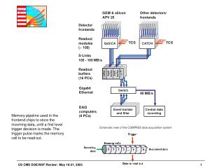
baseline Detector Dependent Unit Receive data from DMB, Format data and send to DCC Detect and report errors Will build 50 boards (36 required) C R A T E C O N T R O L L E R D C C D D U D D U D D U D D U D D U D D U D C C D D U D D U D D U Data Concentration CardReceive data from DDUs, Merge & send data to DAQ Will build 10 boards (4 required) 1 2 3 4 5 6 7 8 9 10 11 12 13 14 15 16 17 18 19 20 21 FED Crates (in USC55) optional • FED board dimensions are 9U x 220mm deep • EMU will have 4 FED crates (2 for each Endcap) • 9 DDUs plus 1 or 2 DCCs in a FED crate • Each DDU reads out 13 CSCs – 200 sector of Endcap
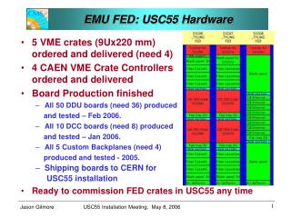
DDU Data Inputs ME4 ME3 ME2 ME1 DDU Data Inputs • Each DDU reads out a 200 slice of Endcap - 13 CSCs (or 13 DMBs) • CSC sectors are rotated between stations to equalize input data rate between DDUs
J1: Standard VME64x, for slow control J3: Custom for data transmission DDU DCC and for TTC control DDU DCC DDU DDU DCC DDU Custom Backplane for FED Crate • Designed for 9 DDU to 1 DCC or 2 DCCs • Each DCC can send data on 1 or 2 SLINKs • Can accommodate various data concentration ratios: • 9 DDU to 1 SLINK - EMU data on 4 SLINKs • 5 or 4 DDU to 1 SLINK - 8 SLINKs (baseline plan) • 3 or 2 DDU to 1 SLINK - 16 SLINKs (for S-LHC?) • 1 DDU to 1 SLINK - 36 SLINKs (for SS-LHC?)
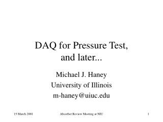
FMM output port VME FPGA Optical Fiber Input (15) Input FPGA Input FIFOs Main FPGA GbE To Local DAQ SLINK Mezz Board GbE FIFO DDU Prototype • Functions • Merge data from 13 DMBs • Perform error checking and status monitoring (CRC, word count, L1 number, BXN, overflow, link status) • Communicates w/FMM • Large Buffer Capacity • 2.5 MB buffer • Average DDU data volume estimated to be 0.4kB per L1A at LHC (@1034 lumi) • Buffer can hold over 6000 events • TTC signals from DCC • Slow control via VME
VME SLINK Output FIFOs Input FIFOs Input FPGAs TTCrx Control FPGA SLINK DDU data J1 backplane DCC Prototype • Data Concentration • Merge data from 9 DDUs • send merged data to central DAQ via 1 or 2 SLINKs • Has two optional GbE spy data path • Fast Control • Receive TTC fiber signals using TTCrx, • Fanout L1A, LHC_clock and other TTC signals to DDUs • Has optional FMM interface GB Ethernet output
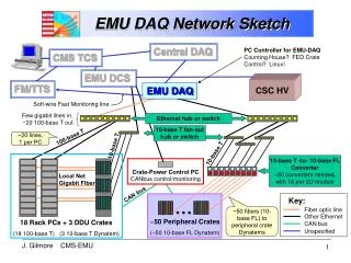
EMU-to-DAQ Test Plans • Can CMS DAQ be used for EMU readout? • What rate can DAQ handle? • SLINK readout limitations (crate location & cable length) • Where does data go? • On-line checks? Data storage? Where & how much? • What rate can EMU provide? • Use cosmic triggers, calibration pulses/fake data, or both? • Before March 17 is good… • Current EMU FED system prototypes are available • Fully compatible with final production system • ~March 21 – April 12 is not so good. • EMU FED production work requires experts at OSU • April 14 or later? • Some new EMU FED boards will be available