Download
1 / 21
210 likes | 404 Views
40G Signal Tap (sniffer) – Yearly Project Part 2 – 40G Signal Tap. Intel: Lan Access Division Technion: High Speed Digital Systems Lab. By: Leonid Yuhananov & Asaad Malshy Supervised by: Dr. David Bar-On. 10G Tap agenda. Goal High Level Specifications: Project definition.

E N D
40G Signal Tap (sniffer) – Yearly Project Part 2 – 40G Signal Tap Intel: Lan Access Division Technion: High Speed Digital Systems Lab By: Leonid Yuhananov& Asaad Malshy Supervised by: Dr. David Bar-On
10G Tap agenda • Goal • High Level Specifications: • Project definition. • HL Block diagram. • Detailed Block View: • Transceiver channel. • Processing block. • Logic Analyzer • Logic Analyzer Interface (LAI). • Plan • Gantt chart. • Deliverables: • Semester 10G. • Yearly 40G. • Demo- TBD
Goal “Tracing 40Gbit Ethernet on a logic analyzer” We want to tap onto 40G traffic and present it in a useful way. • Tap: Listen to the Link. • Sniff the data transmitting on the line. • Present: View data on Logic analyzer. • Parse the data into Ethernet II frames. • Useful: Easy to read and good for debug. • Only the frames we are interested in will be presented.
10G Tap agenda • Goal • High Level Specifications: • Project definition. • HL Block diagram. • Description of main blocks • Detailed Block View: • Transceiver channels. • ALTERA AltGx. • ALTERA 10BaseR-PHY • Alignment FPGA blocks • DDR to Logic Analyzer. • Plan • Gantt chart.
Project Definition • In the Ingress direction: • 4 10G optical lines in differential operation mode. • In the egress direction: • 34x4 channels to logic analyzer. • Display: • Output will be displayed on the logic analyzer in Ethernet II frame structure.
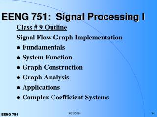
High Level Block Diagram FPGA 4xXAUIx3.125G Transceiver channels AEL2005 SFP+ Optical modules x2 ALTERA AltGx 10.3125Gx2 72 lines x 156.25M x4 Logic Analyzer ALTERAto DDR frequency multipliers 10G word alignerx4 40G wordsaligner 4xXAUIx3.125G Transceiver channels AEL2006 SFP+ Optical modules x2 ALTERA10GbaseR PHY 10.3125Gx2 10.3125Gx2
Descriptionofmainblocks. • SFP+ (optical Module): Converts the optical signal to an electrical one. • Transceiver channel: • AEL2005- converts data to 4xXAUI lines of 3.125G traffic (detailed information is internal) • AEL2006- converts data to 10Gbase-R 10.3125G traffic (detailed information is internal) • ALTERA AltGX – convert 4xXAUI to 72 lines of 64 data and 8 controls. • ALTERA 10GBASER-PHY – convert 10.3125Gtraffic to 72 lines of 64 data and 8 controls. • 10G word aligner – Our logic to align data and generate triggers (as defined at midterm presentation) • 40G word aligner – Our logic to align 4x10G lines to 40G according to 40G protocol • Altera to DDR frequency block – multipliers that reduce amount of lines to logic analyzer by increasing speed.
10G Tap agenda • Goal • High Level Specifications: • Project definition. • HL Block diagram. • Description of main blocks • Detailed Block View: • Transceiver channels. • ALTERA AltGx. • ALTERA 10BaseR-PHY • Alignment FPGA blocks • DDR to Logic Analyzer. • Plan • Gantt chart.
Transceiver channels • Puma AEL2005 - 10GbE LAN PHY/SerDes • Transiving 10G to 4 lanes of XAUI eachone of 3.125G traffic. • NetLogic Microsystems' Puma AEL2005 device is a physical layer transceiver. AEL2005provides full PCS, PMA, and XGXS sub-layer functionality through the consolidation of the receiver and transmitter PHY functions on a single chip along with the integration of encode/decode/alignment logic, FIFOs, on-chip clock drivers, multiple loop-back features and PRBS & Ethernet frame generation & verification for both the line side and the system side.
Transceiver channels • Puma AEL2006-10GbE Dual CDR w/EDC • Transiving 10G HSRXDATA from SFP+ to 10G RXDATA for 10G baseR PHY • NetLogic Microsystems' Puma AEL2006 device is a dual physical layer retimer - compliant with IEEE802.3aq specifications. • The NetLogic Microsystems Puma AEL2006 device provides the consolidation of the receiver and transmitter SerDes functions on a single chip along with on-chip clock drivers, multiple loop-back features and PRBS generation & verification for both the line side and the system side.
ALTERA AltGx • ALTGX – block from Alteramegafunction, used to convert 4x3.125G XAUI lines to 8 words of data and 8 bits of controls • Deserializer • 8/10 protocol • Word aligner • Phase compensation
ALTERA 10G BaseR PHY • 10G BaseR PHY – block from Alteramegafunction, used to convert 10G RXDATA to 8 words of data and 8 bits of controlsSDR XGMII = single data rate XGMII, 72 bits @156.25 Mbps • 10GBASE-R PCS • 10.3125-Gbps physical medium attachment (PMA), • PHY management functions • 10GBASE-R PHY functions: 64b/66b encoding/decoding • scrambling/descrambling • 66b/16b gear-boxing, and data serialization/deserialization
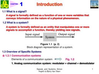
Alignment FPGAblocks • 10G alignment logic (detailed description at part 1) • Rearrangement of data coming from XAUI and 10G-BASER-PHY • Alignment data from beginning of packet • Triggering matched packet (hard coded) • Contains FSM, rewiring blocks and trigger capturing FSMs 10G-BASER-PHY alignment logic x2 XAUI alignment logic x2 72 bits 156.25M not aligned 72 bits 156.25M aligned 72 bits 156.25M not aligned 72 bits 156.25M aligned • Note: Two different logic for two different not aligned data from AltGx and 10GbaseR-PHY
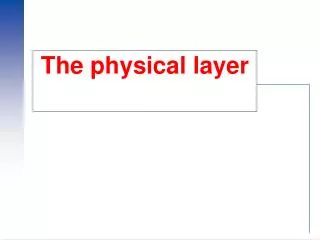
Alignment FPGA blocks • 40G alignment logic • Contains 4 10G alignment blocks • Determining alignment pattern logic • Alignment output according to 40G protocols – FSMs • Redirection of Trigger’s signals • Arrangement data for DDR to Logic analyzer block 72 bits 156.25M aligned 10G-BASER-PHY alignment logic x2 72x4 bits 156.25M Aligned for 40G protocol And DDR multipliers
Logic Analyzer • A logic analyzer is an electronic instrument which displays signals in a digital circuit. A logic analyzer may convert the captured data into timing diagrams, protocol decodes, state machine traces. • TLA7000 Series • 6,528 Logic Analyzer Channels • 500 ps (2 GHz) – serial data • 312.5 ps (3.2 GHz) – signal integrity • 625 ps (1.6 GHz) MIPI
DDR – Double Data Rate • The double data rate is our output to the outer world (Logic Analyzer). • Since we want to utilize less LA pins using higher speeds, a double data rate is required. • Should be considered as a serializer, from 2 or more lines of a certain data rate, to a single line of double or more data rate. • The operation is based on a high speed DeMux, with a round around counter for its select bits.
10G Tap agenda • Goal • High Level Specifications: • Project definition. • HL Block diagram. • Description of main blocks • Detailed Block View: • Transceiver channels. • ALTERA AltGx. • ALTERA 10BaseR-PHY • Alignment FPGA blocks • DDR to Logic Analyzer. • Plan • Gantt chart.
Project Constraints • Exams: we are on the doorstep of the coming exams, that puts work on the project onto low gear if not suspension. • The DDR to soft touch connector: an imperative piece of hardware the is required by our project to interface with the Logic Analyzer. We are currently waiting for its tape out. • A 40G link partner, currently the industry only has 2 other NICs capable of 40GbE, and an IXIA would be an expensive and an unwise purchase, while using the 40G generator by the other team might mask shared problems in the design. • One of our dev boards was fried during testing operation and it is undergoing fixing and rewiring, in the case of a failure to do so, the delivery time of a new board is 3-6 weeks. • We are using MegaCore functions provided by Altera, and as it seems as of today, there seem to be usage limitations concerning operation mode. We may run our design while connected to the computer only, we are working on acquiring the license for the function.
Next • Expand the SFP+ interfacing to all of the connectors to a total of 4. • The on board AEL chip is of different generation (2006), which may prove a double edged sword – being more capable but with the risk of incoherence with the 2005. • The magnitude of the challenge of syncing the 4 connectors is still yet to be clear (it won’t be a walk in the park). • Configuring the AEL 2006. • Since it is a different chip the MDIO write will be different. • It may be that there is no mirror mode to the one the AEL 2005 operates on. • Get 40Gbit link. • A whole new world – 40G is still young in the industry. • Who is our partner? • Latency issues with the Altera might arise with ~200 bit wide busses. • Generating trigger and capturing packets using logic analyzer. • Logic analyzer – a while new device to integrate. • Triggering the LA in sync with the data. • We managed to go inside Altera – now we go outside again. • Integrating it all together with the generation side. • Size of design might start being an issue. • Clock synchronization and pipelining. • Strain on Altera in 40G Rx/Tx (80Gbs data processing no matter how wide will have to go through our processing blocks) • Writing end of project book and presentation.
Thank you all Stay tapped for more