Download
1 / 63
650 likes | 657 Views
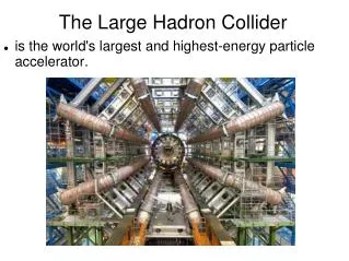
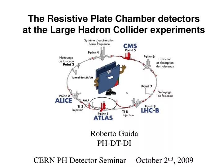
The Resistive Plate Chamber detectors at the Large Hadron Collider experiments. Roberto Guida PH-DT-DI CERN PH Detector Seminar October 2 nd , 2009. Outline. Introduction to the RPC detector Where are the RPC detectors at LHC Main parameters for the design

E N D
The Resistive Plate Chamber detectors at the Large Hadron Collider experiments Roberto Guida PH-DT-DI CERN PH Detector Seminar October 2nd, 2009
Outline • Introduction to the RPC detector • Where are the RPC detectors at LHC • Main parameters for the design • From the design to the production: • An “industrial approach” • Quality control procedure • Requirement for RPC operation at LHC • Effect of background radiation • Rate capability/detector occupancy • Long-term performance – ageing issues • Experience on operation of RPC detectors: • Importance of the gas mixture quality • Effect of the environmental conditions (T + RH) • Gas leak • Conclusions
Outline • Introduction to the RPC detector • Where are the RPC detectors at LHC • Main parameters for the design • From the design to the production: • An “industrial approach” • Quality control procedure • Requirement for RPC operation at LHC • Effect of background radiation • Rate capability/detector occupancy • Long-term performance – ageing issues • Experience on operation of RPC detectors: • Importance of the gas mixture quality • Effect of the environmental conditions (T + RH) • Gas leak • Conclusions
The RPC detector Resistive Plate Counters resistive parallel plate gaseous detector Developed around 1980 in Italy by R. Santonico et al. NIM 187 (1981) 377-380 • 1. Electrodes:HPL made with melamine/phenol resins; Glass; Ceramic • Resistive electrodes: 1010- 1012cm • Internal electrode surface covered with a thin linseed oil layer (~m) • 2. Gap width: 2 mm • 3. High Voltage contacts: graphite paint (~100 m) • Operating pressure: atmospheric pressure • Gas mixture: Ar, C2H2F4, iC4H10, SF6 • Gas flow: 0.2 vol/h • Dimensions: Surface: ~ m2,thickness: 1 cm • Read-out strip: Al/Cu, ~cm
Working principle Ionizing particles passing through the gas are producing primary ionization Primary electrons accelerated in the electric field will start to produce further ionization ntotal: total number e-/Ion E: total energy loss Wi: <energy loss>/(total number e-/Ion)
Gain Charge multiplication Primary e- = first Townsend coefficient • = attachment coefficient = - = effective Townsend coefficient x 20 M 108 Reather breakdown limit
Why the RPC? • Drift chambers (cylindrical geometry) have an important limitation: • Primary electrons have to drift close to the wire before the charge multiplication starts • limit in the time resolution 0.1s • Not suitable for trigger at LHC • + In a parallel plate geometry the charge multiplication starts immediately (all the gas volume is active). • + much better time resolution ( 1 ns) • + less expensive ( 25 €/m2) • However: • -Smaller active volume • Electrical discharge may start more easily • Relatively expensive gas mixture • Quite sensitive to environmental conditions (T and RH)
Some history 1949: Keuffel first Parallel Plate Chamber 1955: Conversi used the “PPC idea” in the construction of the flash chambers 1980: Pestov Planar Spark chambers – one electrode is resistive – the discharge is localised 1982: Santonico development of the Resistive Plate Chamber – both electrode are resistive RPC applications: ‘85: Nadir (n-n\bar oscillation) – 120 m2 (Triga Mark II – Pavia) ‘90: Fenice (J/ n-n\bar) – 300 m2 (Adone – Frascati) ‘90: WA92 – 72 m2 (CERN SPS) ‘90: E771– 60 m2; E831 – 60 m2 (Fermilab) 1992: development of RPC detector suitable to work with high particle rate towards application at LHC 1994-1996: L3 – 300 m2 (CERN-LEP) 1996-2002: BaBar – 2000 m2 (SLAC)
RPC equivalent circuit. HV Ionizing particle Why resistive electrodes? Are the most important improvement with respect to previous generations Time constant for charge development is related to drift velocity and multiplication discharge = 1/vd ~ 10 ns discharge << recharge Time constant for recharge the elementary cell is related to the RC recharge = ~ 10 ms • Since recharge >> discharge the arrival of the electrons on the anode is reducing the electric field and therefore the discharge will be locally extinguished. • the electrode are like insulator after the first charge development • Self-extinguish mechanism
Avalanche signal Streamer signal Towards a new operation regime • Originally RPC were operated in Streamer mode: • Ar-based mixture • Higher signal (100 pC) but also high current in the detector • Voltage drop at high particle rate loss of efficiency poor rate capability (< 100 Hz/cm2) • Operation with high particle rate possible in Avalanche mode: • Freon-based mixture • lower signal ( pC) but also lower current in the detector • Less important high voltage drop at high particle rate good rate capability ( 1 kHz/cm2) R. Santonico et al. ATLAS Muon TDR
RPCs for LHC experiments Where are the RPCs systems at LHC? ATLAS experiment: • Single gap Bakelite RPC • Barrel • - read-out • Active surface 4000 m2 • Expected rate ~ 10 Hz/cm2 • Gas system: • Volume 16 m3 • 94.7% C2H2F4; 5% iC4H10; 0.3 % SF6 • 40% Rel.Humidity • Closed loop operation • Circulation flow 0.5-1 vol/h • 5-10% renewal
RPCs for LHC experiments Where are the RPCs systems at LHC? CMS experiment: • Double gap Bakelite RPC • Barrel and Endcap • read-out • Active surface 4000 m2 • Expected rate ~ 10-100 Hz/cm2 • Gas system: • Volume 16 m3 • 94.7% C2H2F4; 5% iC4H10; 0.3 % SF6 • 40% Rel.Humidity • Closed loop operation • Circulation flow 0.5-1 vol/h • 5-10% renewal
RPCs for LHC experiments Where are the RPCs systems at LHC? ALICE experiment: • Muon Trigger System • Single gap Bakelite RPC • Forward Muon Spectrometer • x-y read-out • Active surface 140 m2 • Expected rate ~ 10 Hz/cm2 • Gas system: • Volume 0.3 m3 • 50.5%Ar; 41.3% C2H2F4; 7.2% iC4H10; 1 % SF6 • 89.7% C2H2F4; 10% iC4H10; 1 % SF6 • 40% Rel.Humidity • Open mode • Flow 0.5-1 vol/h
RPCs for LHC experiments Where are the RPCs systems at LHC? ALICE experiment: • Time of Flight System • Multi-gap glass RPC • Barrel • - read-out • Active surface 171 m2 • Gas system: • Volume 18 m3 • 90% C2H2F4; 5% iC4H10; 5 % SF6 • 93% C2H2F4; 10% iC4H10; 1 % SF6 • Closed loop operation • Circulation flow 0.06 vol/h • 2% renewal
RPCs for LHC experiments Why RPCs for application in LHC experiments need a particular “care”? • Huge (5000 m2 of sensitive area) and very expensive (6 106 CHF) systems (for comparison BaBar was about 2000 m2) • Very long period of operation expected (at least 10 years) • Very high level of background radiation expected • Integrated charge never reached before: 50 mC/cm2 for ALICE and CMS 500 mC/cm2 in ATLAS • Large detector volume basically impossible to operate the gas system in open mode closed loop operation gas mixture quality
Outline • Introduction to the RPC detector • Where are the RPC detectors at LHC • Main parameters for the design • From the design to the production: • An “industrial approach” • Quality control procedure • Requirement for RPC operation at LHC • Effect of background radiation • Rate capability/detector occupancy • Long-term performance – ageing issues • Experience on operation of RPC detectors: • Importance of the gas mixture quality • Effect of the environmental conditions (T + RH) • Gas leak • Conclusions
Identikit of RPC detectors for LHC • Basic parameter for a detector design: • Gap width • Single gap/double gap/multi gap design • Gas mixture • Gas flow distribution • Bakelite bulk resistivity • Linseed oil electrode coating
The RPC detector: gap width The gap width is affecting both time performance charge distribution R = l/ • cluster density (primary clusters) g =const = 18 R > 1 R < 1 Narrow gap better time resolution, but “more critical” charge spectrum (R seems to be the driving parameter) reduce number of primary electrons M. Abbrescia et al. NIMA 471 55-59
The RPC detector: single vs double gap • The double gap layout: • allow to operate at lower (i.e. lower high voltage) • best ration qind/qtot (single 0.7; double 1.4; 3 gaps 0.8) • Better charge distribution • More expensive per unit of active area
The RPC detector: gas mixture • Key parameters: • cluster density (primary clusters) – only gas dependent • first Townsend coefficient (charge multiplication) – gas, HV dependent • attachment coefficient – gas (electronegative and/or quencher), pressure dependent • effective Townsend coefficient = - High gas: high efficiency and low streamer probability at the same ! i.e. for avalanche regime: better Freon ( = 5.5 mm-1) than Ar ( = 2.5 mm-1) Voltage increasing
Charge distribution: avalanche streamer The RPC detector: gas mixture • Key parameters: • Moreover quencher (iC4H10) and electronegative (SF6) gases will help in containing the charge development and reducing the streamer probability M. Abbrescia et al. NIMA 508 142-146 R. Santonico Scientifica Acta Pavia Fraction of streamer vs High voltage:
The RPC detector: gas mixture • Key parameters: • Large are giving also a better charge distribution (constant ) ≤ 4 mm-1 spectrum monotonically decreasing Charge spectrum vs Streamer probability M. Abbrescia et al. NIMA 431 413-427
Waldemar MaciochaAntonio Romanazzi The RPC detector: gas flow distribution Experience says that the gas flow has to be at least 0.3 vol / h even without radiation Is the gas distribution inside the gap the origin of this limit? Is there a space for future improvements? Some preliminary results coming from a finite element simulation: Thanks to inlet outlet spacers The velocity field shows areas in which the gas is hardly moving Gas velocity (m/s) inlets
RPC detector: Bakelite resistivity The detector rate capability is strongly dependent on the Bakelite resistivity. At high particle rate (r) the current through the detector can become high enough to produce an important voltage drop (Vd) across the electrode: s: electrode thickness <Qe>: average pulse charge : bakelite resistivity In order not to lose efficiency Vd < 10 V Therefore r~ 1010W cm The time constant of an elementary cell is lower at lower resistivity: the cell is recovering faster (it is quicker ready again) after a discharge took place inside it.
What is the linseed oil: • Drying oil (consists basically of triglycerides) • Drying is related to C=C group in fatty acid • Cross-linking (polymerization) in presence of air (O2 play important role) due to C=C RPC detector: linseed oil surface treatment • RPC electrodes are usually treated with linseed oil: • better quality of the internal electrode surface • it acts as a quencher for UV photons • better detector performance …but… • More time needed during construction • Ageing problems? (Not observed)
RPC detector: linseed oil surface treatment Few SEM photos (S.Ilie, C.Petitjean EST/SM-CP EDMS 344297): Defect on Bakelite surface possibly covered with linseed oil Thickness of the layer: ~ 5 m The linseed oil layer is damaged by a surface outgassing
RPC detector: linseed oil surface treatment Effect on UV photons hitting the electrode internal surface: UV sensitivity for coated and non coated Bakelite Linseed oil absorbance 5.6 eV 8 eV P.Vitulo NIMA 394 13-20 C.Lu NIMA 602 761-765
RPC detector: linseed oil surface treatment Chamber Performance: With linseed oil coated electrodes Lower current (1/10) Lower noise rate (1/10) M. Abbrescia et al. NIMA 394 13-20
The RPC detector • Summary • Gap width 2 mm: • Good compromise between good efficiency, time resolution and rate capability • More gaps: • Increase time resolution and efficiency • Double gap design: • Best ratio induced/drift charge, therefore best signal/charge ratio • Freon based mixture: • Higher efficiency (at the same gas gain) and lower streamer probability • Bakelite bulk resistivity = 1-6 1010W cm: • Good compromise between high rate capability and low current and noise • Linseed oil treatment: • Lower current and noise rate. No ageing effect observed
Outline • Introduction to the RPC detector • Where are the RPC detectors at LHC • Main parameters for the design • From the design to the production: • An “industrial approach” • Quality control procedure • Requirement for RPC operation at LHC • Effect of background radiation • Rate capability/detector occupancy • Long-term performance – ageing issues • Experience on operation of RPC detectors: • Importance of the gas mixture quality • Effect of the environmental conditions (T + RH) • Gas leak • Conclusions
Pavia Sofia ISR Bari GT HT RPC Barrel Production and Test Sites RPCsproduction and quality certification involve several steps. HPL production and quality control Single gap GT Double gap Chambertest Sites ChamberassemblingSites RB1 in Pavia RB2 & RB4 in Bari RB3 in Sofia (& Bari) 120 RB1 at HT 240 RB2 and RB4 at GT 120 RB3 in Sofia (& Bari)
CMS-RPCQuality Control Further information and results about all QC are stored in our construction database: http://webcms.ba.infn.it/rpc
QC2: The “Bakelite” for RPC detector • More precisely the RPC electrodes are made on High Pressure Laminate: • Several layers of ordinary paper • Passed into a resin bath • Heated and compressed • Finally cut • HPL top and bottom layer produced with more refined paper • Resin bath: • Made of phenolic and/or melamine resins • Different ratio according to the desiderate bulk resistivity • In general, outer layers passed in phenolic resin only (again “low” resistivity) • All the Bakelite for RPCs has been produced in Italy: Chimica Pomponesco (later on Frati Laminati) near Pavia After the production Quality control Resistivity range r20 = 1- 6 1010W cm Average Roughness range Ra ≤ 0.2 mm 4000 slabs produced (about 15000 m2)
V0 R V How to measure r ~ 1010 - 1011Wcm • The idea for the automatic system was to have the possibility: • to measure on 9 different points of the slabs • to use guard rings and hence • to measure also the surface resistivity • to increase the measurements productivity up to > 100 slabs/day r = k V0/(V/R) k = geometrical factor (98.17) V0= 500 V R = 10 or 100 kW
Outline • Introduction to the RPC detector • Where are the RPC detectors at LHC • Main parameters for the design • From the design to the production: • An “industrial approach” • Quality control procedure • Requirement for RPC operation at LHC • Effect of background radiation • Rate capability/detector occupancy • Long-term performance – ageing issues • Experience on operation of RPC detectors: • Importance of the gas mixture quality • Effect of the environmental conditions (T + RH) • Gas leak • Conclusions
Effects of background radiation It is imperative that the design of a pp experiment at the LHC takes account of the hostile radiation environment engendered at high luminosity (CMS Letter of Intent, CERN-LHCC 92-3, 1 Oct. 1992) • Two mechanisms: • instantaneous particle rate detector occupancy • cumulative effects ageing • Detector occupancy: • Related to the background radiation detector efficiency • RPC are very efficient in detecting charged particle • Efficiency for neutral radiation is very low…but if the particle rate is high enough… • Ageing: • Related to the integrated particle fluence, dose and current in the detector
CMS Max flux: Barrel ~10 Hz/cm2 Forward ~ 50-100 Hz/cm2 Barrel Forward Charged background ATLAS Max flux: Barrel ~5 Hz/cm2 Forward ~ 10 Hz/cm2 m, p fluxes in Hz/cm2 n, g fluxes in kHz/cm2
Neutral background Barrel Forward CMS experiment Max flux: Barrel ~460 Hz/cm2 Forward ~ 10-50 kHz/cm2 Energy: between 20 keV - 100 MeV Max Integrated dose 10 years: (Barrel and most Forward) < 1 Gy CMS-RPC total integrated charge for Barrel region 50 mC/cm2
35 x 35 cm2 double gap RPC: • Gap 1 oiled • Gap 2 not oiled Detector occupancy • Given the expected background (particles + fluxes) we have: • Measured the RPC sensitivity to it • Performed simulation study for the final configuration on the experiment RPC used for the sensitivity measurement:
Neutron and gamma sensitivity Two main tests performed: 252Cf source neutron beam Summary of the results: R. Guida et al. NIMA506 101-109 R. Guida et al. NIMA508 79-82
Expected induced rate Simulation results over a wide energy range: Experimental results As an example, considering the gamma and neutron fluxes for the innermost barrel muon station (MB1) in CMS we have: n rate: 460 Hz/cm2 <En> 5 MeV 1 Hz/cm2 g rate: 240 Hz/cm2 <Eg> 1.4 MeV expected rate 4 Hz/cm2
Expected induced rate ATLAS results (numbers are in Hz/cm2): Similar number 10 Hz/cm2 In conclusion, the magnitude of induced rate is of some Hz/cm2. but….we may have possible surprises due to new phenomena and….are the simulation completely reliable over the full range? In any case we have a big margin… RPCs proved to have a rate capability close to 1 kHz/cm2 Now we have to look at the long term effect (ageing)…
Ageing test • Test for possible effect proportional to the fluence. For example: • verify RPC performance after a working period equivalent to at least 10 LHC years • Fluorine compounds and others pollutants production and their effects on the chambers performance • possible long term effects of the close loop gas system on the chambers performance (accumulation of pollutants) • ….
The Gamma Irradiation Facility CERN experimental area where a muon beam is available together with an intense (650 GBq 137Cs) gamma source. Several tests performed from 1999-2004. Since last year specific test (optimization of the gas purification in closed loop) restarted. The GIF was used for LHC…GIF++ will be available (?) for ageing test in view of SLHC
The detectors: some examples 11 single gaps Two categories of chambers: prototypes and “final detectors” 3 final chambers many final double gaps 2001-2004 2008-…. CMS test CMS + PH-DT-DI test Integrated charge: 70 mC/cm2 45 mC/cm2 15 mC/cm2 15 CMS-Barrel years 9 CMS-Barrel years 3 CMS-barrel years Gas system: Open mode Closed loop Open + closed mode
Increased by a factor 510 Detectors performance: humidified gas RPC community discovered that dry gas produce an increase in the Bakelite resistivity Higher resistivity lower rate capability, i.e. lower efficiency at high rate Started to flow humidified gas (40-50% RH) Bakelite resistivity: Detector efficiency recovery: Recovery of RPC9 with the moist mixture: maximum efficiency vs time at Source Off and ABS1 M. Abbrescia et al. NIMA533 102-106 R. Guida et al. NIMA594 140-147
Purifiers: Closed loop gas circulation • Large detector volume (~16 m3 in ATLAS and CMS) • use of a relatively expensive gas mixture • closed-loop circulation system unavoidable. • Nowadays with 5-10 % of fresh gas replenishing rate cost is 700 €/day • But…. • Several extra-components appear in the return gas of irradiated RPCs • Detector performances can be affected if impurities are not properly removed
Gas analysis results: chromatography However, some open questions… Purifiers: - better configuration (?) - effectiveness - lifetime - regeneration process Recirculation: which fraction (?) Fresh mixture A zoom of the same region for the mixture before and after the purifiers: Not all extra peaks can be filtered, with any combination of the tested filters (signals 2, 4 remain) It seems that the Ni filter produce or enhance one extra signal (number 8)
Gas analysis results: chromatography • Many extra components identified in the return mixture from detector • Operated with open mode gas system • Under high gamma radiation • Concentration of the order of 10 ppm • Mainly hydrocarbons • other Freon R. Guida et al. IEEE2008 Proceeding
Gas analysis results: Fluoride • Two method used to evaluate the Fluoride concentration in the exhausted gas: • Fluoride specific electrode • HPLC (liquid chromatography) Measured concentration as a function of time: basically no HF produced with radiation On and RPC Off The production rate seems RPC dependent but………actually it scales nicely with the drawn current Analysis Pavia 2002 Analysis Pavia 2002