Download
1 / 53
610 likes | 798 Views
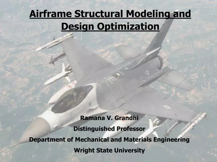
Airframe Structural Modeling and Design Optimization. Ramana V. Grandhi Distinguished Professor Department of Mechanical and Materials Engineering Wright State University. VIM/ITRI Relevance.

E N D
Airframe Structural Modeling andDesign Optimization Ramana V. Grandhi Distinguished Professor Department of Mechanical and Materials Engineering Wright State University
VIM/ITRI Relevance • Computational Mechanics is a field of study in which numerical tools are developed for predicting the multi-physics behavior, without actually conducting physical experiments • Study the behavior of -- materials -- environmental effects -- strength/service life -- signature, radar cross-section -- etc. • Experiments are conducted mainly for validation and verification
Modeling of individual components Vertical Tail Fuselage Missile Elevator Nose Wing
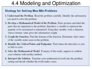
Simulation Based Design Physical Modeling Simulations Cost Functions Design Variables Performance Limits Design Optimization Forging Extrusion Rolling Sheet Drawing ManufacturingSchemes Simulations Database Generation Experiments Rapid Access/Decision Making
Generate a Finite Element Model of the structure Perform a Finite Element Analysis Optimize the design for improved performance and reliability Airframe Design Create a Parametric definition, Structural Model
Structural model Tip chord Leading edge Trailing Edge Root chord
Simulation Based Design - Goals • Study the complex multi-physics behavior of the warfighter at hypersonic speeds and in combat environment • Study the behavior of shocks in transonic region due to flow non-linearities – vehicle response and control • Develop high fidelity models for accurate performance measures • Analyze wing structures with attached missiles. • Reduce the modern vehicle development costs by performing simulations rather than costly physical experiments. --quickly and accurately analyze anything we can imagine
Development Challenges • High fidelity simulation of integrated system behavior -- structures/aerodynamics/control/signature/plasma • Design of lightweight high performance affordable vehicles • Increase the structural safety, reliability and predictability • Design critical components such as wing structures by including non-linear behavior models. • Facilitate simulation of large-scale airframe structures in interdisciplinary design environment. • Develop analysis procedures which are reliable for reaching the goal of “certification by analysis” instead of expensive trial-and-error component test procedures.
Material Characteristics • Exceptional strength and stiffness are essential features of airframe parts. • Low airframe weight boosts aircraft performance in pivotal areas, such as, range, payload, acceleration, and turn-rate. • Advanced composite materials and high temperature materials offer reduced life-cycle costs – but manufacturability challenges
Generating a Finite Element Model • Finite element model is a discretized representation of a continuum into several elements. where is the elemental stiffness matrix is the elemental displacement matrix is the elemental load matrix Triangular element Quadrilateral element θ
Finite Element Analysis Equations describing the behavior of the individual elements are joined into an extremely large set of equations that describe the behavior of the whole system where assembled stiffness matrix assembled displacement matrix assembled load matrix Finite Element model is used to study deflection, stress, strain, vibration, and buckling behavior in structural analysis Assembly of finite elements
Finite Element Analysis (FEA) • It is one of the techniques to study the behavior of an Airframe structure by performing: • Stress Analysis • Frequency Analysis • Buckling Analysis • Flutter Analysis • Missiles and their influence • Multidisciplinary design Optimization
Stress Analysis • A structure can be subjected to air loads, pressure loads, thermal loads, and dynamic loads from shock or random vibration excitation and the airframe responses can be analyzed using FEA techniques. • FEA takes into account any combination of these loads. • A detailed finite element analysis, shows the stress distribution on a F -16 aircraft wing.
Forces acting on the wing Leading edge Tip chord Trailing Edge Root chord
Stress distributions along the wing Minimum Stress at tip chord Maximum Stress at root chord
Finite Element Analysis (FEA) • It is one of the techniques to study the behavior of an Airframe structure by performing: • Stress Analysis • Frequency Analysis • Buckling Analysis • Flutter Analysis • Missiles and their influence • Multidisciplinary design Optimization
Frequency Analysis • The dynamic response of a structure which is subjected to time varying forces can be predicted using finite element analysis. • Frequency Analysis is performed to determine the eigenvalues (resonant frequencies) and mode shapes (eigenvectors) of the structure. An eigenvalue problem is represented as: where is an eigenvalue (natural frequencies) is an eigenvector (mode shapes) • The model can be subjected to transient dynamic loads and/or displacements to determine the time histories of nodal displacements, velocities, accelerations, stresses, and reaction forces.
Structural model 26.5’’ Shear Elements Quadrilateral Elements 108’’ Rod Element 48’’ Mode shapes of the Wing Mode 1: Bending mode (9.73 Hz)
Structural model 26.5’’ Shear Elements Quadrilateral Elements 108’’ Rod Element 48’’ Wing Mode Shapes Mode 2: Torsion mode (34.73 Hz)
Fluid- Structure Interaction Fluid structure interaction plays an important role in predicting the effect of a flow field upon a structure and vice-versa. This interaction helps in accurately capturing the various aerodynamic effects such as angle of attack/deflections/ shocks. .. . + + Kx = A(t) = Aerodynamic forces M x C x Structure Flow Field
Tip chord Leading edge Trailing Edge Root chord Occurrence of Shocks Wing Model Shock on the wing
Finite Element Analysis (FEA) • It is one of the techniques to study the behavior of an Airframe structure by performing: • Stress Analysis • Frequency Analysis • Buckling Analysis • Flutter Analysis • Missiles and their influence • Multidisciplinary design Optimization
Buckling Analysis Buckling means loss of stability of an equilibrium configuration, without fracture or separation of material. Buckling mainly occurs in long and slender members that are subjected to compressive loads. Long Slender member F = compressive load Before Buckling After Buckling
Buckling Phenomena in a Sensorcraft AFRL/VA Sensorcraft Concept Finite Element Model Buckling Phenomenon 1562 grid pts 3013 elements Next
Finite Element Analysis (FEA) • It is one of the techniques to study the behavior of an Airframe structure by performing: • Stress Analysis • Frequency Analysis • Buckling Analysis • Flutter Analysis • Missiles and their influence • Multidisciplinary design Optimization
Flutter Analysis • Flutter is an aerodynamically induced instability of a wing, tail, or control surface that can result in total structural failure. • Flutter occurs when the frequency of bending and torsional modes coalesce. • It occurs at the natural frequency of the structure.
Finite Element Analysis (FEA) • It is one of the techniques to study the behavior of an Airframe structure by performing: • Stress Analysis • Frequency Analysis • Buckling Analysis • Flutter Analysis • Missiles and their influence • Multidisciplinary design Optimization
Missiles and their influence Wing Tip Missile Under wing Missile
Influence of a Missile Missile Influence Structural dynamic effect Aerodynamic effect Flutter speed of the wing increases/decreases depending on missile placement. As the center of gravity moves towards the leading edge the flutter speed increases. Design optimization is performed to place the missile at an optimal position. The natural frequency of the wing reduces due to increased mass This shows that frequency is inversely proportional to mass.
Wing Model with Missile at the tip Structural Model Mode 1: Bending Mode (3.8 Hz) Missile Frequency of the wing first mode without a missile : Bending mode (9.73 Hz)
Wing Model with Missile at the tip Mode 2: Torsion mode (7.84 Hz) Structural Model Frequency of the wing second mode without a missile : Torsion mode (34.73 Hz)
Finite Element Analysis (FEA) • It is one of the techniques to study the behavior of an Airframe structure by performing: • Stress Analysis • Frequency Analysis • Buckling Analysis • Flutter Analysis • Missiles and their influence • Multidisciplinary design Optimization
Design Optimization • Optimization is required for: • Improved performance • High reliability • Manufacturability • Higher strength • Less weight • Tools used for optimization are: • Sensitivity Analysis • Approximation Concepts • Graphical Interactive Design • Conceptual and Preliminary Design • Design with Uncertain and Random Data
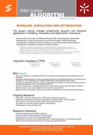
1.62E-02 9.58E-02 2.91E-03 -3.35E-03 -1.04E-02 -1.71E-02 -2.37E-02 -3.04E-02 -3.07E-02 -3.74E-02 -4.37E-02 Sensitivity Analysis • Sensitivity analysis measures the impact of changing a key parameter in system response. • The plot shows that the elements near the root chord are the most sensitive, and change in these element parameters will effect the stress distribution Sensitivity analysis plot
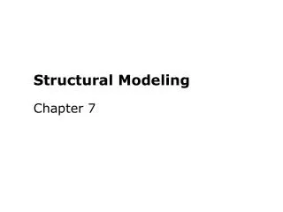
4.23E-01 4.08 E-01 3.74 E-01 7.05E-01 7.05 E-01 2.71 E-01 2.37 E-01 2.03 E-01 1.68 E-01 1.34 E-01 1.00 E-01 Optimization of design variables(Thickness) Thickness Design Variables Optimum Thickness Distribution
Simulation Based Design Physical Modeling Simulations Cost functions Design variables Performance limits Design Optimization Forging Extrusion Rolling Sheet Drawing ManufacturingSchemes Simulations Database Generation Experiments Rapid Access/Decision Making
Forging Simulation Billet Top die Bottom die Conventional approach (Peanut Shaped Billet)
Challenges in Process Simulation • Modeling of forging dies • Collection of material flow-data Thermal expansion Heat conductivity Flow stresses • Appropriate boundary conditions. • Nonlinear material behavior • Optimal forging process parameters Press velocity Die and Billet temperature • Die Shape Optimization Preforming Stages Preform Shapes • Infinite paths to reach the final shape
Optimal Design Objectives • Design for manufacturability • Reduce material waste, i.e. achieve a net shape forging process by optimizing material utilization and scrap minimization. • Eliminate surface defects, i.e. laps and voids. • Eliminate internal defects, i.e. shear cracks and poor microstructure. • Minimize effective strain and strain-rate variance in workpiece. • Design optimal process parameters such as forming rate (die velocity) and initial workpiece and die temperatures.
Preform Design Engineering Preform Design Methods: • Empirical guidelines based on designer’s experience • Computer aided design/geometric mapping • Backward Deformation Optimization Method (BDOM) Current Design Methods: • Backward tracing method • Numerical optimization method
Preform Design of the billet Trimming the scrap Reducing the scrap Section After Die fill
Backward Simulation – Preform Design Optimization Approach
Scrap Comparison for differentinitial billets 12 % Scrap Peanut Shape 5 % Scrap Preform Shape
Crankshaft Forging - Initial Stage Top Die Billet Bottom die