Download
1 / 25
260 likes | 433 Views
Boundary Conditions. Based on Slides Prepared By Eileen Poeter, Colorado School of Mines. Sources and Sinks. Types of Boundary Conditions. 1) Specified Head: head is defined as a function of space and time (could replace ABC, EFG)

E N D
Boundary Conditions Based on Slides Prepared By Eileen Poeter, Colorado School of Mines Sources and Sinks
Types of Boundary Conditions 1) Specified Head: head is defined as a function of space and time (could replace ABC, EFG) Constant Head: a special case of specified head (ABC, EFG) 2) Specified Flow: could be recharge across (CD) or zero across (HI) No Flow (Streamline): a special case of specified flow where the flow is zero (HI) 3) Head Dependent Flow: could replace (ABC, EFG) Free Surface: water-table, phreatic surface (CD) Seepage Face: h = z; pressure = atmospheric at the ground surface (DE)
Three basic types of Boundary Conditions After: Definition of Boundary and Initial Conditions in the Analysis of Saturated Gournd-Water Flow Systems - An Introduction, O. Lehn Franke, Thomas E. Reilly, and Gordon D. Bennett, USGS - TWRI Chapter B5, Book 3, 1987.
DIRICHLETConstant Head & Specified Head Boundaries Specified Head: Head (H) is defined as a function of time and space. Constant Head: Head (H) is constant at a given location. Implications: Supply Inexhaustible, or Drainage Unfillable
NEUMANNNo Flow and Specified Flow Boundaries Specified Flow: Discharge (Q) varies with space and time. No Flow: Discharge (Q) equals 0.0 across boundary. Implications: H will be calculated as the value required to produce a gradient to yield that flow, given a specified hydraulic conductivity (K). The resulting head may be above the ground surface in an unconfined aquifer, or below the base of the aquifer where there is a pumping well; neither of these cases are desirable.
CAUCHYHead Dependent Flow • Head Dependent Flow: • H1 = Specified head in reservoir • H2 = Head calculated in model • Implications: • If H2 is below AB, q is a constant and AB is the seepage face, but model may continue to calculate increased flow. • If H2 rises, H1 doesn't change in the model, but it may in the field. • If H2 is less than H1, and H1 rises in the physical setting, then inflow is underestimated. • If H2 is greater than H1, and H1 rises in the physical setting, then inflow is overestimated.
Free Surface Free Surface: h = Z, or H = f(Z) e.g. the water table h = z or a salt water interface Note, the position of the boundary is not fixed! Implications:Flow field geometry varies so transmissivity will vary with head (i.e., this is a nonlinear condition). If the water table is at the ground surface or higher, water should flow out of the model, as a spring or river, but the model design may not allow that to occur.
Seepage Surface Seepage Surface: The saturated zone intersects the ground surface at atmospheric pressure and water discharges as evaporation or as a downhill film of flow. The location of the surface is fixed, but its length varies (unknown a priori). Implications:A seepage surface is neither a head or flowline. Often seepage faces can be neglected in large scale models.
Natural and Artificial Boundaries It is most desirable to terminate your model at natural geohydrologic boundaries. However, we often need to limit the extent of the model in order to maintain the desired level of detail and still have the model execute in a reasonable amount of time. Consequently models sometimes have artificial boundaries. For example, heads may be fixed at known water table elevations at a county line, or a flowline or ground-water divide may be set as a no-flow boundary.
Natural Hydrologic Features as Boundaries • Boundary can be assigned to hydrologic feature such as: • Surface water body • Lake, river, or swamp • Water table • Recharge and evapotranspiration or source/sink specified head • Impermeable surface • Bedrock or permeable unit pinches out
Natural No-Flow Boundary • Hydraulic conductivity contrasts between units • Alluvium on top of tight bedrock • Assume GW does not move across this boundary • Can use ground-water divide or flow line
Note ground-water divide shifts after development—may or may not be a good no-flow BC T.E. Reilly, 2000
Practical Considerations • Boundary conditions must be assigned to every point on the boundary surface • Modeled boundary conditions are usually greatly simplified compared to actual conditions
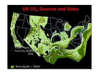
Injection and Pumping Wells • Flux across the Water Table • Leakage Sources and Sinks
Same model options used to represent boundary conditions are used to represent internal sources and sinks • Specified flux for wells • Specified head for lakes, rivers, drains Sources and Sinks
Wells—an internal boundary condition at a point—thought of as a stress to the system • A well is a specified flow rate at a point • Can be pumping or injecting water • Withdrawals or injection may vary in space and time • Node may represent entire thickness of a cell (which often represents an aquifer) • MODFLOW’s MNW package remedies some issues
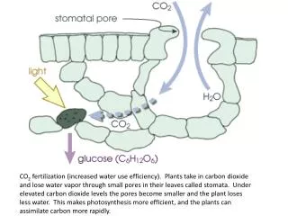
Flux across the Water Table (free surface boundary) • Treated as an internal source or sink (Dupuit assumptions) • May vary with time and space • Array(s) of flux values • Variety of methods for estimating water table fluxes • Directly to/from surface or through unsaturated zone
Estimating water table fluxes • Recharge • Infiltrated water that crosses the water table and becomes part of the ground water system • Discharge • Ground water that moves upward across the water table and discharges to the surface or to the unsaturated zone
Recharge • No one universally applicable method • Traditionally based on percentage of precipitation • Significant spatial and temporal variations • Accommodated by Zones • Rates adjusted during calibration • Often largest unknown
Recharge Methods • Water Balance Models • With MF either pre-process or code modifications • PRMS and GS-FLOW • Unsaturated Zone Models
Discharge • Evapotranspiration occurs when • Plants remove water from the water table • Direct evaporation from the water table • May be head-dependent (if water-table too far below land surface ET is unlikely) • Varies in space and time
Leakage • Movement of water through a layer of material that has a lower hydraulic conductivity • Enters or leaves depending on relative head • Magnitude and direction may vary in time • Source: aquifer, river, or lake • Sink: aquifer, river, lake, drain, springs, or seeps • Type of head-dependent boundary • General head boundaries • Drains (only act as sinks)
Ground-water / Surface-water Interaction • Hydraulic head in aquifer can be equal to elevation of surface-water feature or allowed to leak to the surface-water feature • Usually defined as a “Constant-Head” or “Specified Head” Boundary or “Head-dependent flow” boundary • If elevation of SW changes, as with streams, elevation of the boundary condition changes
How a stream could interact with the ground-water system T.E. Reilly, 2000