Download
1 / 36
360 likes | 496 Views
WP7 - Power Couplers. Three main tasks (LAL-Orsay)* Design and construction of new proto-types Conditioning studies Construction of titanium-nitride coating bench. * with invaluable advice from colleagues at DESY. New proto-types. Three new proto-type designs

E N D
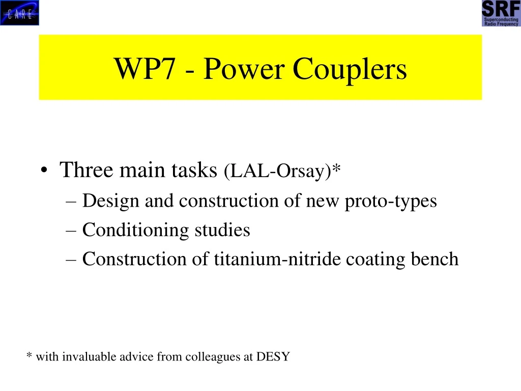
WP7 - Power Couplers • Three main tasks (LAL-Orsay)* • Design and construction of new proto-types • Conditioning studies • Construction of titanium-nitride coating bench * with invaluable advice from colleagues at DESY
New proto-types • Three new proto-type designs • TTF-V coupler – based on TTF-III design • proto-types in construction • Traveling Wave 60 mm coupler – different window architecture, • proto-types in construction. • “Modified” TTF-III coupler, • engineering drawings only
TTF-V Proto-type • Essentially = TTF-III “warm” part + 62 mm f “cold” part. • Increased diameter for higher power handling and to push back multipactor power levels. • Candidate coupler for a two x 9 cell ILC cavity • Engineering drawings and technical specifications completed. • Tender exercise won by ACCEL • Four such couplers will be built for high power tests. Delivery in spring 2006. • Will be subsequently used for studies on RF conditioning times.
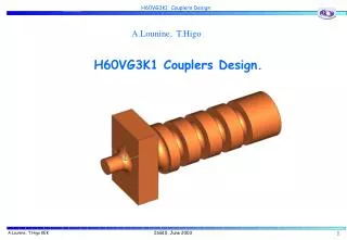
TW60 Coupler Proto-type • Radically different from DESY coupler • uses “thin” planar ceramic windows. • Warm transition is matched with reduced-height wave-guide. • Cold window matched with reactive impedance elements on inner co-ax. • Four couplers to be built by ACCEL. • High power tests planned for 2006. Delivery in summer 2006.
Modified TTF-III coupler Reduced fabrication tolerances. Remote control of Qext. Central antenna biased for e- p.u.
DESY bench Titanium-nitride coating bench Industry to be consulted with view to building bench “according to specification” Full technical specification written. First contacts with potential suppliers. They all propose coating by sputtering. Windows to date coated by evaporation. We will perform tests on sample ceramics to evaluate sputtering w.r.t evaporation. Delivery time ~ 6 months. Alternative approach – collaborate with CARE partners, DESY INFN-Legnaro, on “home-built” system.
Conditioning of TTF-III couplers Controlled incrementing of amplitude and length of RF pulse to their full operating values.
WP 8 Tuners CEA, DESY, INFN-Milan, IPN-Orsay, TU-Lodz Main goals - (see highlight talk by P. Sekalski) • Development of fast tuners based on piezoelectric and/or magnetostrictive elements. • Fast and slow tuner integration. • Aim to develop tuners capable of compensating 1 kHz of detune, allowing the cavities to operate in a stable fashion at 35 MV/m. • Long lifetime is a major issue - aim to develop tuners allowing 10 years of operation.
WP8 conclusions Piezo Tuner System (CEA) and Blade Tuner (INFN) will bereadyfor cold test with cavitiesin 2-3 months. Piezostack characterization is almost finished (IPNO). Tested actuators are immune to radiation, may work for required lifetime and fulfill requirements forVUV-FEL, X-FELandILC. The magnetostrictive tuner (TUL) was run successfully at LHe temperature. Ready for test with a cavity in one month. Automatic feed forward algorithmfor piezostack-based system for Lorentz force compensation works correctly (DESY, TUL). It damps detuning from 180Hz (15MV/m) down to below 10Hz in2 iterations.
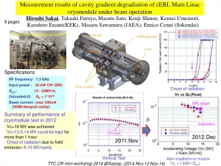
Detuning without piezo compensation 180Hz FLAT TOP Detuning with piezo compensation < 10Hz Results Measurement done in cavity 5, ACC1 VUV-FEL field gradient ~20 MV/m
WP 10 Cryostat Integration Tests Integrated Tests of components from other work-packages. • Provide horizontal test bench to test components from other work-packages at cryogenic temperatures • Nine-cell TESLA cavity @ high RF power with; • New Cold Tuning Systems ( WP8 ) • Piezoelectric and Magneto-strictive Tuners (WP8 ) • Fundamental Power Couplers ( WP7 ) First task (WP10) : Get CryHoLab ready for High Power operation @ 1.3 GHz on 9-cell cavity
Nine-Cell Cavity in CryHoLab C45 cavity - 20 MV/m - and TTF III coupler (warm part) cavity power coupler thermal sensors
CRYOGENIC OPERATION ( January 2005 ) • He tank filling – Cool-down (4.2K & 1.8K) – Thermal Insulation • Improve Thermalisation of support table
FPC Conditioning 300 K (detuned cavity) 1MW / 1 ms 3.8 Hz Pionicpump 5.10-8 mbar
RF Measurements August 2005 4 K (tuned cavity) 900 kW / 250 ms 0.88 Hz no flat top FE with X-rays detection : 1 7 mSv/h Measurement to be improved ( He instabilities )
Cold Tuning System & Piezo Actuators ( Warm Test ) Lorentz force detuning (20 MV/m) September 2005 RF lab. (WP8 : assembly , pre-loading ) stepping motor (Phytron) PZT (Noliac)
CTS & PZT : cold test in CryHoLab November 2005 December 2005 Magnetic shield improvement Static : m metal Dynamic : coils (20 mG) + cryoperm structure around the cavity (sheets provided by DESY)
WP-10 2005 schedule Preparation ( cavity - cryogenic test ) : Jan. 2005 Preparation ( high power coupler - RF ) : July-Aug. 2005 1st series ( CEA tuner with Noliac PZT ) : Dec. 2005 Magneto-strictive tuner CryHoLab removal and re-installation : Jan. 2006 (9 months ?) 2nd series ( IN2P3 PI piezo – LAL coupler) : autumn 2006
WP 11 – Beam Diagnostics Two principal tasks Development of Beam Position Monitors – CEA and DESY – Re-entrant cavity type. Development of a Diffraction Radiation monitor for beam size and emittance – INFN-Frascati and INFN-Roma2
LO signal at monopole frequency given by a PLL 9 Mhz Low pass filter 50Mhz Band pass filter 1.25Ghz Digital electronics Δ/Σ Band pass filter 1.7Ghz Low pass filter 50Mhz BPM LO signal at dipole frequency given by a PLL 9 Mhz Hybrid 180° WP11 Beam Diagnostics - BPM • BPM in TTF/ACC1 (old type, < 10µm) New BPM design - improved resolution (< 1 mm), fast time resolution ~ 10 ns, more reliable feed-throughs, improved discrimination between monopole and dipole signals, more compatible with cryogenic environment.
BPM Schedule • Sept. 05 - Dec. 05: Fabrication of the 1st BPM cavity (TTF room temperature). • Oct.05 : Test and commissioning of the old type BPM in ACC1 • Oct. 05 - Jan. 06: Fabrication of the 2nd BPM cavity (TTF cryogenic temperature). • Jan. 06: RF tests with beam at DESY • Feb.06 - Apr. 06: Validation of the RF board + Programming and validation of the digital electronics. • May 06 - June 06: Tests at DESY (2 weeks) on the cavity which is at room temperature with its electronics but without control-command interface. The tests will be done with displacement of the beam to evaluate the noise, the dynamic range and to calibrate the system. • Feb. 06 - Sept. 06: Installation and preparation of the cold BPM cavity. • Oct. 06: Tests of the cold cavity with the beam and electronics without the control-command interface. • Nov. 06 - Feb. 07: Programming of the control-command interface. • March 07: Tests of the cold cavity and its electronics.
New sub-task for WP11- HOM based BPM • RF Cavity Dipole Higher Order Mode signals BPM Centering accuracy and ‘BPM’ resolution better than 50 µm (TTF, 2004) • The 40 cavities of TTF will be equipped with the SLAC-DESY HOM electronics with the aid of CARE manpower.
WP 11 Beam Diagnostics / Beam Emittance and Size Monitor based on Diffraction Radiation Use DR from a fine slit as a non-intercepting monitor Installation status • Diffraction Radiation target was installed in June 2005 • Optical system and lead shielding was installed in Sept. 2005 • The CCD camera is now in place • The high sensitivity Hamamatsu CCD will be installed ONLY during the DR measurements • The transport optics in the by-pass has been checked • We are ready to test the whole set-up, depending on the TTF linac schedule • Dedicated beam time will be requested for the next machine development period in February-March 2006
DR radiator • The target was made using a lithography technique starting from a silicon-nitride wafer and opening the slit by means of chemical etching. • The surface roughness, the planarity of the target mounted in the holder, and the sharpness of the aperture borders were all carefully checked.
Optical system • There are 2 lenses, one to image the beam, the other to produce the DR angular distribution • f=500 mm double convex with antireflection coating • f=250 mm achromatic doublet for beam imaging • 2 interferential filters at 800 nm and 450 nm • A polariser to select only the vertical component • The camera holder is movable and is compatible both for Basler CCD camera and Hamamatsu camera
Optical system Lens with f=500 mm for DR angular distribution Interferential filter at 450 nm Interferential filter at 800 nm Glenn-Thompson polarizer Lens with f=250 mm for beam imaging CCD camera Electronic control of targets and cameras via precision stepper motors Driven by an industrial PC using a custom driver is ready
Present status (from M. Castellano, Legnaro, 20/10/05) • All the hardware is installed. • We are ready to take first data, as of our milestone of 31/12/2005. • At the present time, the schedule of the machine does not allow this possibility before the end of the year. • Adequate beam time will be requested for the machine development period of February-March 2006.
Concluding remarks • The detailed presentations at the Legnaro meeting, and two highlights talks from this week, show evidence of substantial progress on all SRF work-packages from 7 through to 11. • Several milestones have been met and others are on the verge of being met and will be completed in 2006. • Fuller details than have been given here will be available in the SRF 2005 annual report. Thank you for your attention !
Light sensor Pumping port Waveguide to coax transition Room temperature Isolation vacuum flange Qext tuning knob Warm coax Ø 60 mm Z=50 Ohm Cold coax Ø 40 mm Z=70 Ohm 70 K point 4 K point Isolating Kapton foil Room temperature window e- 2 pick up e- 3 pick up Cold window e- 1 pick up Flange to cavity Qext tuning rod Conditioning TTF-III Couplers
Vacuum Oven Class 10 clean room Ultra pure water system Klystron Modulator Infra-structure for coupler conditioning
Coupler preparation • Ultra-sonic cleaning using ultra-pure water (r = 18 MW.cm) with 1% Tickopur solution. • Rinsing with UP water. • Drying in class 10 clean room area • Baking in vacuum oven. • Assembly of cold coupler parts to WG test box in Class 10 clean room. • Assembly of warm parts. • Leak test and in-situ bake-out • Connection of couplers to high power source under mobile laminar flow (class 100). Labour intensive process !!
Warm Part Assembly in Local Clean Room Local clean room Coupler test stand