Download
1 / 25
250 likes | 358 Views
Xilinx ML310 board based on VirtexII-PRO programmable device. Students: Tsimerman Igor Firdman Leonid Supervisor: Rivkin Ina. Agenda. Project goals Board overview System overview Project Status Part B project description Project schedule. Project Goals.

E N D
Xilinx ML310 board based on VirtexII-PRO programmable device Students: Tsimerman Igor Firdman Leonid Supervisor: Rivkin Ina Technion Digital Lab Project
Agenda Project goals Board overview System overview Project Status Part B project description Project schedule Technion Digital Lab Project
Project Goals Making a list of all “on board” peripherals Activation of peripherals Writing ML310 board and peripherals User Guide Connecting and activating PS2 keyboard with ML310 board. Technion Digital Lab Project
Board Overview Technion Digital Lab Project
Board Overview ML310 High-Level block diagram • Directly connected to FPGA • peripherals. • All have softcore controllers (Can • be added through EDK). • Low-level drivers supplied. • Ready to be used in • OS/Stand-Alone mode • Indirectly connected to FPGA • peripherals. • Accessible through PCI bridge. • All HW controllers exist and can • be used in OS mode with • appropriate drivers. Technion Digital Lab Project
Board Overview Directly connected to FPGA peripherals • DDR Memory • Registered 256 MB PC3200 double data rate (DDR) Dual Inline Memory Module (DIMM) with an industry-standard 184-pin count. • Access to memory is through software application by pointers. • Memory check programs are provided. • Serial port FPGA UART (RS-232 standard) • Serial port (J4) is connected to the XC2VP30 FPGA (U37) through a MAX3232 Transceiver (U7). It can be accessed by simply implementing a UART in the FPGA fabric. Technion Digital Lab Project
Board Overview Directly connected to FPGA peripherals • IIC/SMBus Interface • The Inter Integrated Circuit (IIC) bus provides the connection from the CPU to peripherals. It’s a serial bus with data and clock bidirectional signals. • The IIC/SMBus interface serves as an interface to one master device and multiple slave devices. • SMBus uses IIC as its backbone. • Serial Peripheral Interface • Serial Peripheral Interface (SPI), is a serial interface like the IIC bus interface. There are three differences: the SPI operates at a higher speed, there are separate transmit and receive data lines, and the device access is chip-select based instead of address based. • The ML310 employs a single SPI device which is a 25LC640, 64 kb EEPROM. Technion Digital Lab Project
Board Overview Directly connected to FPGA peripherals • System ACE CF Controller • The System ACE CF controller is the primary means of configuring the XC2VP30 on the ML310 board through the JTAG interface. • System ACE CF controller can be used to facilitate general-use, non-volatile storage. The System ACE CF controller provides an MPU interface for allowing a microprocessor to access the CompactFlash memory, enabling the use of the CompactFlash card as a file system. • GPIO • The ML310 Hardware Platform provides direct GPIO access to eight LEDs for general purpose use, and provides indirect access to a 16-pin connector (J13) that interfaces the ML310 to a 2-line by 16-character LCD display, AND491GST. A simple register interface handles access to the XC2VP30 GPIO signals. Technion Digital Lab Project
Board Overview Directly connected to FPGA peripherals • PM1, PM2 connectors • Each connector has 40 differential pairs and several • power and ground pins. Together, the two PM connectors • on the ML310 support 158 high-speed I/O pins that can be • user defined. The PM1 and PM2 signals are as follows: • • 8 RocketIO MGT pairs (32 pins total) • • 42 LVDS pairs (can be used as 84 single-ended I/O • at 2.5V) • • 1 LVDS clock pair • • 38 single-ended I/O • 12 at 2.5V • 26 at 3.3V • • 2 single-ended 2.5V clocks • • 2 pins not connected Technion Digital Lab Project
Board Overview Indirectly accessible (trough PCI bus) peripherals • The onboard 33 MHz, 32-bit PCI bus is connected to fixed PCI devices, listed below, that are part of the ML310 board: • ♦ Two 3.3V keyed PCI add-in card slots (P5 and P3) • ♦ Two 5.0V keyed PCI add-in card slots (P6 and P4) • ♦ Intel, GD82559, 10/100 PCI Ethernet NIC • ♦ Ali, M1535D+, PCI South Bridge • The Virtex-II Pro PPC405 processors can gain access to the primary PCI bus through the EDK • PCI Host Bridge IP. EDK also provides PCI Arbiter IP. Technion Digital Lab Project
Board Overview Ethernet cores • Intel, GD82559, 10/100 PCI Ethernet NIC • Fast Ethernet controller with an integrated 10/100 Mb/s physical layer device for PCI board LAN designs. • Ethernet MAC (Media access controller) • Provided softcores for Ethernet implementation are: OPB/PLB Ethernet MAC. • There is also “Lite” version of OPB MAC with minimal necessary functions. • All low level functions are provided. Note: For Ethernet testing appropriate protocol must be implemented (TCP/IP for example). There is an option to use “internet sniffer” program In HOST with crossed cable connected in order to detected any data packets. Technion Digital Lab Project
Board Overview ALi South Bridge Interface, M1535D+ (U15) ALi M1535D+ supports the following features: ♦ 1 parallel and 2 serial ports ♦ 2 USB ports ♦ 2 IDE connectors ♦ GPIO ♦ SMBus interface ♦ AC’97 audio codec ♦ PS/2 keyboard and mouse ♦ Flash ROM Technion Digital Lab Project
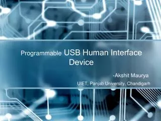
Board Overview Peripherals connected trough Ali south bridge • USB Connector Assembly • The M1535D+ USB is an implementation of the Universal Serial Bus Specification Version 1.0a that contains two PCI Host Controllers and an integrated Root Hub. • No drivers are provided. • Serial & Parallel Ports Interface Connector Assembly • The ALi M1535D+ provides access over the PCI bus to two serial ports and one parallel port. Technion Digital Lab Project
Board Overview Peripherals connected trough Ali south bridge • IDE Connectors (J15 and J16) • Supports a 2-channel UltraDMA-133 IDE master controller independently connected to a primary 40-pin IDE connector (J16) and a secondary 40-pin IDE connector (J15). • No drivers are provided. • GPIO Connector (J5) • There are 15 GPIO pins connecting the ALi M1535D+ to the 24-pin GPIO header (J5). These can be accessed through the ALi M1535D+ by way of the PCI bus. Technion Digital Lab Project
Board Overview Peripherals connected trough Ali south bridge • System Management Bus Controller • The SMBus host controller in the M1535D+ supports the ability to communicate with power related devices using the SMBus protocol. • AC’97 Audio Interface • The ALi South Bridge Super I/O controller has a built-in audio interface that is combined with a standard audio codec (AC’97), LM4550. Features available to the user are as follows: • ♦ AC’97 Codec 2.1 Specification compliant • ♦ Codec variable sample rate support • ♦ 32-voice hardware wave-table synthesis • ♦ 32 independent DMA channels • ♦ 3D positioning sound acceleration • ♦ Legacy Sound Blaster compatible • ♦ FM OPL3 emulation • ♦ MIDI interpretation • ♦ MIDI MPU-401 interface Technion Digital Lab Project
Board Overview Peripherals connected trough Ali south bridge • PS/2 Keyboard and Mouse Interface Connector (P2) • The ALi M1535D+ has a built-in PS2/AT keyboard and PS/2 mouse controller. The PS/2 keyboard and mouse ports are connected to the ALi M1535D+ through standard DIN connectors. • No drivers provided. • In order to use keyboard with ML310 board in stand alone mode, one have to implement low level drivers that will enable software access to dedicated registers on Ali, trough PCI bus. • In OS mode PS2 controllers will be recognized and standard keyboard drivers will be installed. • Flash ROM (U4) • The ALi South Bridge supports 4 Mb Flash memory interface. The ML310 provides connectivity to an AM29F040B 4 MB (512 K x 8 bit) flash memory (U4) via the Ali M1535D+ ROM interface. Technion Digital Lab Project
System Overview • The following peripherals were activated and used: • UART • GPIO – LCD and LEDs • DDR • OPB – PCI bridge • Ali SB • Keyboard controller • Keyboard Technion Digital Lab Project
DIMM Power PC 405 LEDs RS232 LCD conn. GPIO UART DDR PCI Bridge + IPIF PLB/OPB Bridge PS2 System Overview Overall system block diagram Xilinx ML310 Virtex II Pro LCD PLB OPB Serial Port PCI ALi South Bridge KBC Keyboard Technion Digital Lab Project
System Overview Building a system • The system is built from a scratch using EDK BSB (Base system builder). • The software was written preserving all modularity rules, • therefore each SW component can be added or removed from application project separately. • Important notes • One should pay attention when defining PCI-bridge memory range, so it will cover all PCI devices memory demands (In our project default state – 64K has been used). • PCI memory space can be divided into memory and IO mapping. It is critical to define IO window when addressing IO mapped devices. • The one should pay special attention when DDR module is used. BSB default DDR parameters is not always match with current DDR module. In this case, the parameters should be configured manually in MHS and UCF files. Technion Digital Lab Project
System Overview Initializing a system • PCI initialization: • Enable OPB – PCI bridge in PCI master mode • Ali SB initialization: • Super IO reset • Enabling keyboard controller • KBC initialization: • KBC reset • KBD enable (Set 1 mode and interrupt mode activated ) • Note: • All initialization operations are done by writing to configuration spaces of appropriate device (OPB – PCI bridge, Ali SB, KBC) Technion Digital Lab Project
PCI initialization is performed • through PCI bridge configuration • registers PCI bus scanning: Device 1 - Ali Audio Device 2 - Ali SB Device 3 - Ali Modem Device 7 - Enet Mac Device 9 - PCI – PCI Brg Device 11 - Ali IDE Device 12 - Ali Pwr Mgt Device 15 - Ali USB cntr • Super I/O (ALi) and KBC • Initialization. • KBC & KBD self tests. • Enabling Keyboard in • interrupt mode. System Overview Initializing a system Technion Digital Lab Project
Keyboard Intel IntrC 8259 KBD cntr 8042 Xilinx ML310 PS2 Virtex II Pro X2 (clock, data) ALi Power PC 405 IRQ1 Non critical intr SBR_INTR Opb_InrC System Overview KBD interrupt block diagram • The PCI Ali South bridge device uses a separate interrupt line that connects to the FPGA via schematic net SBR_INTR. • Anytime an interrupt occurs within the Ali SB, it generates an interrupt on SBR_INTR. • SBR_INTR can be connected directly to PowerPC or via OPB_INTC. In our project second option is implemented for generic causes. Technion Digital Lab Project
Project Status • List of all on board peripherals – done • Short description of each peripheral was made • Activation of UART, LCD, LEDs, DDR - done • Attempt to activate and testing Ethernet • Early core physical connection attempt was made • Achieved access to PCI peripherals - done • Configured OPB - PCI bridge • Configured Ali SB • Connected and activated PS2 KBD & KBC in interrupt mode Technion Digital Lab Project
Show me your best Power PC 405 User core Generator PLB/OPB Bridge Part B (with Intel cooperation) Preliminary system block diagram Virtex II Pro • Generator is creating random • data patterns. • PowerPC and User IP doing • the same logical function in data • analyzing. • HW vs. SW performance is tested • under same conditions and frequency • fluctuations. • The goal is to find a frequency in which • PowerPC fails to achieve correct output. PLB OPB Technion Digital Lab Project
Project schedule • Part A: • Writing ML310 board and peripherals User Guide document.<Till 31.4.2005> • Part B: • General design considerations and high level block diagram. <Weeks 3-5> • Generator construction, test and debug. <Weeks 6-8> • User core for data analyzes construction, test and debug. <Weeks 9-10> • Power PC SW creation, test and debug. <Weeks 11-12> • Building all the system, test, debug and simulation. <Weeks 13-14> • Writing Part B project final report . <Weeks 15-16> Technion Digital Lab Project