Download
1 / 29
290 likes | 399 Views
EUV Imaging Spectrometer (EIS): Instrument Checkout, Performance Verification and Initial 90 Day Observing Plan. Extended Solar Optical Telescope Meeting 17 th – 20 th April, 2006 at NAOJ Len Culhane for the EIS Team. SUMMARY. EIS Instrument Outline Instrument Performance Tests

E N D
EUV Imaging Spectrometer (EIS):Instrument Checkout, Performance Verification and Initial 90 Day Observing Plan Extended Solar Optical Telescope Meeting 17th – 20th April, 2006 at NAOJ Len Culhane for the EIS Team
SUMMARY • EIS Instrument Outline • Instrument Performance Tests • Post-launch activities • Spacecraft • EIS Engineering • EIS Calibration • EIS Initial Science Plan • EIS Planning Tool Software • Conclusions
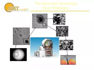
Primary Mirror Entrance Filter CCD Camera Front Baffle Grating EIS Optical Diagram
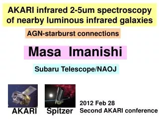
EIS Effective Area Primary and Grating: Measured - flight model data used Filters: Measured - flight entrance and rear filters CCD QE: Measured - engineering model data used Following the instrument end-to-end calibration, analysis suggests that the above data are representative of the flight instrument
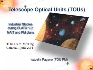
Detected photons per 11 area of the Sun per 1 sec exposure. EIS Sensitivity
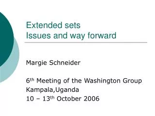
Dual CCD Camera Grating Primary Mirror Shutter Slit/Slot Wheel Filter Holder Installed Instrument Control Unit Principal EIS Subsystems for Commissioning
Instrument Performance Tests Optical Performance Primary mirror:Coarse mirror motion Fine mirror motion Slit/slot:Slit width Repeatability of slit position Position of slits with respect to slots Grating:Focus check post-launch DetectorSlit curvature and orientation Magnification vs. wavelength Plate scale Variation of above around orbit Pointing:Short-term stability Around orbit variation
Instrument Performance Tests Photometric Assess throughput/ photometric calibration: Compare with pre-launch – Te, ne insensitive line ratios in QS Detector: Full well Linearity Flat field Dark current Charge Transfer Efficiency (CTE) Co-alignment: SOT – He II 256Å slot images with magnetograms and chromospheric images XRT – Fe XV 284Å slot images with XRT images Spectral lines: Spectral resolution Dispersion Monitor average count ratesforQS, AR, CH and Flares
Post-Launch Activities • Spacecraft • Systems commissioning (~ 21 days; tbc) • EIS Engineering • Pre-filter enclosure opening (6 days) • Post-filter enclosure opening (4 days) • EIS Calibration • EIS specific observations (~ 5 days) • Trial synoptic observations (2 days) • EIS Initial Science • 90 day initial observing plan (90 days) • EIS Planning Tool Software
1. Spacecraft Launch sequence t = X – Liftoff t = X + 77 min – begin array deployment t = X + 80 min – complete array deployment t = X + 83 min – begin Sun acquisition t = X + 94 min – complete Sun acquisition Spacecraft systems commissioning t = X + 21 days (TBC) – complete systems commissioning Note: Useful to have some instrument testing enabled during this interval e.g. QCM readings, CCD bakeout Allow minimum of 24 hrs for out-gassing before first turn on
Pre-Clamshell Opening StudyActivity 2. EIS Engineering Tests [Day/Orbit] • COMENG01 ICU on - software checks (memory) [1 / 2] Day 1 is Day 21 • COMENG02 MHC on – load code, QCMs on [2 / 1] • COMENG20 Initial QCM readings [2 / 2] • REGENG00 QCM1/2; readings once per day [2 / 2] • COMENG03 Op. heaters on for temp. stabilisation [2 / 3] • COMENG04 Mechanism tests for Slit/Slot selection [4 / 1] • COMENG05 Mechanism tests for Shutter [4 / 2] • COMENG10 CCDs on - load/initiate test sequence [5 / 1] -startCamera data assessment [5 / 2] Note:X days elapsed time allowed for complete EIS out-gassing and camera data assessment before front filter doors opened
2. EIS Engineering Tests Post-Clamshell Opening StudyActivity [Day/Orbit • COMENG99 Opening of filter enclosure doors [1 / 1] Day 1 is • Day (21 + X) • COMCAL00 Test sequences of full CCD [1 / 2] • COMENG07 Mechanism tests for Fine Mirror[2 / 1] • COMENG08 Mechanism tests for Grating– grating focus [3 / 1] • COMENG06 Mechanism tests for Coarse Mirror [5 / 1]
3. EIS Calibration and Performance Verification StudyActivity • COMCAL00 Test sequences of full CCD – top-half then bottom-half to establish solar image position; assign 512 pixel y-range • COMCAL01 Test sequences with 512 pixel hardware window for range of exposure times to check wavelength range, QE, solar response • COMCAL02 Wavelength calibration; execute full spectral scans in different solar regions e.g. AR, QS, CH – compare with lab calibration • COMCAL03 Intensity calibration; QS observations to determine detector efficiency - Te, ne insensitive line ratios; compare with pre-launch QE • COMCAL04 CCD dark current; confirm stable CCD operating temperature in nominal orbit so that dark current can be estimated
3. EIS Calibration and Performance Verification StudyActivity • COMCAL05 Measure CCD flat-fields using EIS LEDs • COMCAL06 Establish EIS pointing and alignment • - network and limb observations with SOT; EIS 40” slot/He II 256Å • - AR and limb observations with XRT; EIS 40” slot/Fe XV 284Å • COMCAL07 Determine CCD particle background; measure as f (orbit position) • COMCAL08 Sit and stare with changing slit/slot; • - establish mechanism repeatability • - determine line profiles for different slit/slot selections • - identify any variation with orbit position • - measure EIS plate scale; compare with XRT • - determine slit curvature • - determine magnification as f (l) • COMCAL09 Scattered light estimate; off-pointing from bright AR
3. EIS Calibration and Performance Verification StudyActivity • COMCAL10 Trial synoptic observation – full spectral survey • - Observe structure-free quiet Sun and network • - Observe a suitable AR if one is available • - Complete spectral coverage, field of view and observing time TBD • COMCAL11 Trial synoptic observation - solar equator survey • - Use EIS coarse pointing mechanism • - Observe four 10 arc min x 8 arc min fields of view • - Raster each field with 40” slot and 2 minute cadence • - Approximately two hours for complete limb-to-limb survey • Following their development, these synoptic observations should be undertaken • routinely at a frequency to be agreed
4. Initial Science Plan Background • Aim of outline observing plan is to achieve critical science goals in the first three months after commissioning • Goals identified but not yet prioritized: - Sun’s status in the period after launch will influence EIS and mission observing strategy on a weekly/daily basis • Plan will need to be detailed and further enhanced
4. Initial Science Plan Line Lists • Include three lines in ALL studies for a consistent dataset throughout the mission – core lines • Core line list is: - He II → 256 Å, Fe XII → 195 Å, Ca XVII → 192.8 Å • Selection based on line strength and temperature range • Additional lines included as appropriate for each separate science objective
4. Initial Science Plan Principal Topics • Flare trigger and dynamics: - Spatial determination of evaporation and turbulence in a flare • Active region heating: - Spatial determination of v, Te and ne in active region structures • Quiet Sun and coronal hole boundary: - Establish relationship between different types of quiet Sun event Boundary Conditions • If solar conditions permit, observing time will be split evenly between topics • An active region will be tracked if possible • For AR with highly sheared magnetic field, EIS will be in flare mode to respond to XRT's trigger • Otherwise observe quiet Sun and coronal holes for long periods (> 12 hrs) • If no active regions but a quiet prominence, concentrate on this
4. Initial Science Plan Flare Trigger and Dynamics • Spatial determination of evaporation and turbulence in a flare • - Fast raster on pre-selected AR with a complex magnetic topology • - Spectral imaging mode with 40” slot for a flare-productive AR • - Flare trigger response from 250” slot to observe early velocity shifts • - Line selection: core line list and Fe XXIV - 192 Å, Fe XV - 284 Å • - FOV 200" X 200" with 2" slit • - Cadence for 1 raster: 2.5 min with 1 s exposure • - Windows to be wide enough for velocities of ~ 400 km/s (> 30 pixels)
4. Initial Science Plan Active Region Heating: • Spatial determination of v and ne in AR loops for range of Te values • High time cadence sit and stare observations • - Spectral imaging with 40” slot/2s cadence to observe new dynamic phenomena • - Alternate with 1” slit/2s cadence • - Line selection: core lines and Fe XIII – 202 Å, - 203 Å • Spatial variation raster observations • - Large raster (256” x 256”)/2” slit/20 sec cadence to observe AR global changes • over several hours • - Alternate with smaller raster (128” x 128”)/1” slit/40 sec cadence for detailed • velocity measurements (± 3 km/s) • - Line selection: core lines and Si VII – 275 Å, Mg VI – 269 Å, Fe X – 190 Å, • Fe XI – 180 Å, Fe XIII – 202 Å, - 203 Å, Fe XIV – 274 Å, Fe XV – 284 Å, • Fe XVI – 263 Å, Ca XIV - 193.8 Å, Si X – 258 Å • For suitable AR, follow from disc centre to limb comparing disc/limb structures
4. Initial Science Plan Quiet Sun Studies: • Correlate coronal Te, ne and v with magnetic topology inferred from SOT • Detailed study of corona above two supergranule cells; • - Alternate 60” x 512” rasters with slot (40”) and slit (1”) • - Spectral imaging (40” slot) for 50s cadence study of changes in morphology • - Spectral imaging (1” slit) for high resolution 50s cadence spectra at fixed QS • locations; insert 40” images for context • - Line selection: core lines andSi VII – 275 Å, Mg VI – 269 Å, Fe X – 190 Å, • Fe XI – 188 Å, Fe XIII – 202 Å, - 203 Å, Si X – 258 Å, - 261Å • Detailed study of corona above bright point or explosive event; • - Raster, slot and field of view selections as above • - Also run sit and stare mode • - Line selection as above • Detailed study above a coronal hole boundary • - Raster, slot and field of view selections as above • - Also run sit and stare mode • - Line selection as above
5. EIS Planning Tool Software • Planning tool software is in SSW • Users will need to install the EIS SolarSoft tree • Study Definition • Line Lists • Raster Definition • Study Definition • Planners then export studies to ASCII format • E-mail a formatted file and a science case to a dedicated account at MSSL
EIS Core Science Programme • AR Heating → dynamic phenomena in loops • Coronal/Photospheric velocity field comparison in AR • Coronal Seismology → waves in AR structures • AR Helicity content → CMEs, magnetic clouds • Evolution of trans-equatorial Loops • Flare produced plasma → source, location and triggering • Flare reconnection → inflow and outflow • Quiet Sun transient events → network, network boundaries, CH boundaries, size scales • CME Onsets → dimming, filaments, flux-ropes, flaring AR, trans- equatorial Loops • Evolution of large coronal structures → streamers, large-scale reconnection, slow Solar Wind
Some Possible Joint Observations • Solar-B Instruments: • Active Region study campaign (SOT/EIS/XRT) • Emission measure distributions in AR structures (EIS/XRT) • AR helicity content and CME launches (SOT/EIS/XRT) • Magnetic topologies in small events (SOT/EIS/XRT) • Network and intra-network small event energies and velocities (EIS/SOT) • Plasma and magnetic structures above Coronal Hole boundaries (EIS/SOT) • Reconnection flows in flares (EIS/XRT) • Other Missions: • CME launching, topology and magnetic clouds (Solar-B, STEREO, ACE) • CME dimming outflow velocities; their relation to CMEs (Solar-B/EIS, STEREO) • Trans-equatorial loop and filament eruptions (Solar-B/EIS, XRT, STEREO) • Coronal (EIT) waves and their relation to CMEs (Solar-B/EIS, XRT, STEREO) • Intensity and velocity studies of waves in AR structures (Solar-B, TRACE, SDO) • Impulsive flares and sub-surface wave propagation (Solar-B, TRACE, SDO)
Conclusions • After an instrument outline, necessary EIS performance tests were described • Following the spacecraft commissioning of ~ 20 days, EIS checkout should begin • Useful to have some overlap of EIS and spacecraft work • Three major science areas are described as suitable for the first 90 days of observation – subject to Sun’s status • EIS planning tool programmes – line list, raster and study construction codes, are described • EIS core mission science programme is listed along with some possible joint observations