Download
1 / 20
200 likes | 343 Views
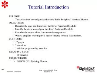
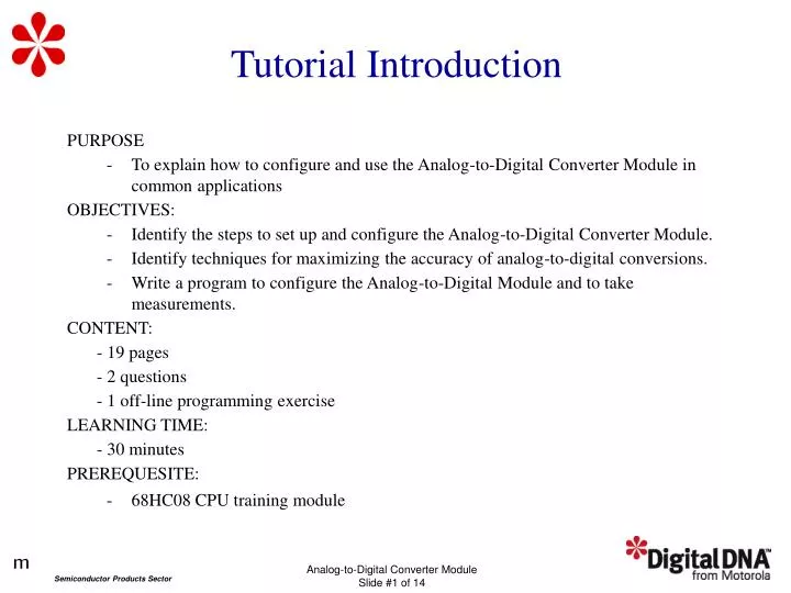
PURPOSE To explain how to configure and use the Analog-to-Digital Converter Module in common applications OBJECTIVES: Identify the steps to set up and configure the Analog-to-Digital Converter Module. Identify techniques for maximizing the accuracy of analog-to-digital conversions.

E N D
PURPOSE To explain how to configure and use the Analog-to-Digital Converter Module in common applications OBJECTIVES: Identify the steps to set up and configure the Analog-to-Digital Converter Module. Identify techniques for maximizing the accuracy of analog-to-digital conversions. Write a program to configure the Analog-to-Digital Module and to take measurements. CONTENT: - 19 pages - 2questions - 1 off-line programming exercise LEARNING TIME: - 30 minutes PREREQUESITE: 68HC08 CPU training module Tutorial Introduction
ADC Module Features • 8-bit or 10-bit resolution • Linear successive approximation with monotonicity • Single conversion and continuous conversion modes • Conversion complete indication by flag or interrupt • Selectable ADC input clock
ADC Module Pins ADC input pins are shared with Port B I/O pins. MC68HC908GP32
Configuring the ADC • Configure VDDAD • - Connect VDDAD to the same voltage as VDD. • - Use external filtering to ensure a clean power voltage • - Route VDDAD carefully and place bypass capacitors close to the package. • Connect VSSAD to the same voltage as VSS. • Separate VREFH and VREFL.
ADC Voltage Conversion • VADIN should not exceed the analog supply voltages. • If VREFH< VADIN< VREFL, the ADC performas a linear conversion. • If VADIN = VREFH, the result is $FF. • If VADIN = VREFL, the result is $00. • The conversion is monotonic and has no missing codes.
ADC Module Registers • ADC Status and Control Register (ADSCR) • ADC Data Register (ADR) • ADC Clock Register (ADCLK)
ADCStatus and Control Register (ADSCR) COCO — Conversions Complete 1 = Conversion completed (AIEN = 0) 0 = Conversion not completed (AIEN = 0)/CPU interrupt (AIEN = 1)
ADC Clock Register (ADCLK) ADIV2–ADIV0 — ADC Clock Prescaler Bits
Calculating Conversion Time 16 to 17 ADC cycles ADC frequency Conversion Time = • Conversion starts after a write to the ADSCR register • One conversion will require between 16 and 17 • ADC clock cycles to complete. = 16 µs or 17 µs with 1 MHz ADC clock
Improving Conversion Accuracy • Reduce noise in the A/D subsystem: • - Separate noisy signals from the A/D signals. • - Reduce the noise coupling. • - See application note AN1059/D, System Design and Layout Techniques for Noise Reduction in MCU Based Systems. • Allow for A/D on-current stabilization. • Minimize source impedance. • Average the results of multiple conversions.
Question If the input voltage, VADIN, is equal to VREFL, what is the conversion result? Click on your BEST choice. a) $00 b) $FF c) All values between $00 and $FF d) none of the above
Question Which of these steps minimizes the noise injected into the A/D converter? Click on your BEST choice. a) Separate noisy signals from A/D inputs b) Reduce noise coupling c) Stabilize the A/D on-current d) Minimize source impedance e) All of the above
ProgrammingExercise • Write a program to configure the 68HC908GP32 ADC for measurements. • - Use ADC channel 0 for input. • - Set the ADCLK to 1MHz ADC clock. • - Turn off the COP and LVI. • - Display results on a set of LEDs. • - Use Port D to drive the LEDs. • Write a subroutine to perform the ADC measurement. • - Identify ADC input channel in accumulator. • - Verify that the port DDR bit is cleared. • - Return conversion result in accumulator.
Exercise Solution - Main Program ADSCR equ $003C ;analog-to-digital status/ctrl reg COCO. equ 7 ;conversion complete flag in ADSCR ADR equ $003D ;analog-to-digital data reg ADCLK equ $003E ;analog-to-digital clock reg ADIV0. equ 5 ;ADC input clock ÷ 2 bit ADIV1. equ 6 ;ADC input clock ÷ 4 bit org FLASH Reset mov #FF, CONFIG1 ;make port D an output for LEDs ;LEDs will show ADC results in binary ; mov #%01100000,ADCLK ;my PCB uses a 8MHz crystal oscillator ;so divide ADC input clock by 8 ;to give recommended 1MHz ADC clock bclr 0,DDRB ;make PTB0 the ADC input main clra ;I chose ADC0, but could use chan 0-7 jsr adc_meas ;take the measurement on ADC0 coma ;LEDs are negative logic on my PCB sta PTD ;display the result bra main ;start main loop over again
Exercise Solution - Main Program ADSCR equ $003C ;analog-to-digital status/ctrl reg COCO. equ 7 ;conversion complete flag in ADSCR ADR equ $003D ;analog-to-digital data reg ADCLK equ $003E ;analog-to-digital clock reg ADIV0. equ 5 ;ADC input clock ÷ 2 bit ADIV1. equ 6 ;ADC input clock ÷ 4 bit org FLASH Reset mov #FF, CONFIG1 ;make port D an output for LEDs ;LEDs will show ADC results in binary ; mov #%01100000,ADCLK ;my PCB uses a 8MHz crystal oscillator ;so divide ADC input clock by 8 ;to give recommended 1MHz ADC clock bclr 0,DDRB ;make PTB0 the ADC input main clra ;I chose ADC0, but could use chan 0-7 jsr adc_meas ;take the measurement on ADC0 coma ;LEDs are negative logic on my PCB sta PTD ;display the result bra main ;start main loop over again
Exercise Solution - Subroutine *********************************************************************** * SUBROUTINE NAME: adc_meas REVISED DATE: 01/02/2000 * * * * PURPOSE: perform A-to-D conversion on one channel of the ADC * * * ENTRY CONDITIONS: ADCLK register set to give 1MHz ADC clock * * Desired ADC input channel on accumulator * * One port DDR bit cleared for that channel * * * * EXIT CONDITIONS: Conversion result on accumulator * *********************************************************************** adc_meas ora #%00100000 ;select continuous conversion mode ; along with user-selected channel sta ADSCR ;turn on ADC and wait for one whole brclr COCO.,ADSCR,* ; conversion cycle to stabilize lda ADR ;clear the COCO bit by reading ADR brclr COCO.,ADSCR,* ;this time take the real measurement mov #%00011111,ADSCR ;got it - now turn off the ADC lda ADR ;retrieve the ADC measurement result rts ;return with result in accumulator
Exercise Solution - Enhancements • Use an averaging algorithm to take measurements. • Pass arguments using the stack. • Enbable interrupt events to report conversion status. • Include an error-handling routine.
Tutorial Completion • - ADC Module Configuration • - ADC Measurements • - A/D Conversion Accuracy