Download
1 / 7
70 likes | 208 Views
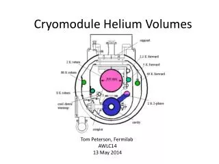
Helium Bag Readiness. Scattering chamber Clamshell flange (not here yet) “Coffee can” collimator. Electron Beam. 20 H target. E Plane E Plane. 0.005” Polyurethane Balloon (sides only). 10 m mylar foil. Front wire chamber. 10 m Mylar Balloon.

E N D
Scattering chamber Clamshell flange (not here yet) “Coffee can” collimator Electron Beam 20 H target E Plane E Plane 0.005” Polyurethane Balloon (sides only) 10 m mylar foil Front wire chamber 10 m Mylar Balloon Upgraded Rear wire chamber
Transport of low energy protons (200-600 MeV/c) from target through BigBite to MWDC • Transport protons using helium a few mm above atmospheric pressure. Almost as good as using vacuum. More convenient and cheaper. • Use company that makes polyurethane helium filled balloons of all shapes and sizes. Polyurethane skin 0.15 - 0.005 “ thick. Will lose helium slowly over a few days. Test leakage rate. • Flexible enough to have limited angular movement of BigBite. Show sample material. • Stretched over circular snout fixed to scattering chamber and hot glued • Stretched over rectangular angle aluminum attached to wire chamber frame and hot glued • Investigate stability of the system and radiation damage of polyurethane and glue and measure helium loss rates.
Stretch over aluminum support frame and hot glue poly and terminate with 10 m mylar Stretch over “coffee can” collimator and hot glue Shape of Polyurethane Helium Filled Balloon 157.8 cm 18 Deg Side view 33.8 cm 18 Deg 82.3 cm 5 cm 122.9 cm 33.1 cm 5 cm 2 Deg 25.2 cm Bottom view 38.7 cm 44.0 cm 206.2 cm
Test on Balloons • Need to always keep inflated above atmospheric pressure • Monitor during the experiment. This is crucial. • Mechanical stability of of joints and seams and leak rates • On the polyurethane balloons and mylar balloons • Conduct radiation damage test on both types. • Effects on hot glue joints • Effects on seams • Effects on polyurethane
Balloon Milestones • March • Design/Draft shape of polyurethane helium containment balloon • Design Coupling balloon to chamber • Order sample polyurethane balloon material • April • Order prototype polyurethane balloon ( 0.005” thick) and prototype and 10 m mylar “pillow shape” balloon. • Order two extra balloons for protecting PMTs from helium leaks • Design Helium gas handling system for balloon • May • Test all prototype balloons for helium leak rate and radiation damage • Test gas handling system. • June-July • Evaluate test results and make modifications. Decide on many balloons and type.Purchase final balloons • August • Assemble flanges, collimator, window, gas handling system, and balloon for further testing. • September , November, and December • Continue checking out system and measure loss rates over long term