Download

1 / 15
201 likes | 507 Views
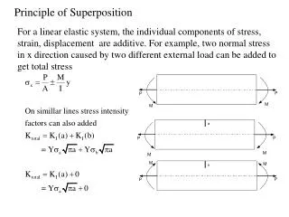
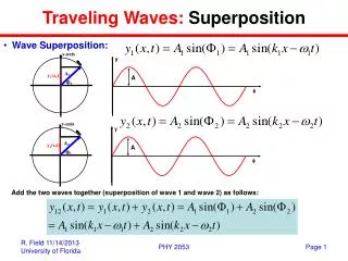
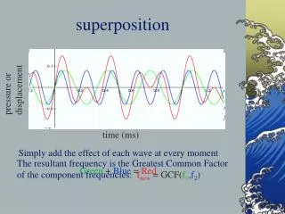
Superposition. Objective of Lecture. Introduce the superposition principle Provide step-by-step instructions to apply superposition when calculating voltages and currents in a circuit that contains two or more power sources. Any combination of voltage and current sources. Superposition.

E N D
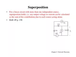
Objective of Lecture • Introduce the superposition principle • Provide step-by-step instructions to apply superposition when calculating voltages and currents in a circuit that contains two or more power sources. • Any combination of voltage and current sources.
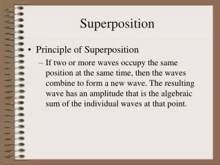
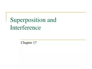
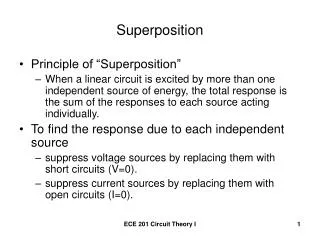
Superposition • The voltage across a component is the algebraic sum of the voltages across the component due to each independent source acting upon it. • Thecurrent flowing through across a component is the algebraic sum of the current flowing throughcomponent due to each independent source acting upon it.
Usage • Separating the contributions of the DC and AC independent sources. Example: To determine the performance of an amplifier, we calculate the DC voltages and currents to establish the bias point. The AC signal is usually what will be amplified. A generic amplifier has a constant DC operating point, but the AC signal’s amplitude and frequency will vary depending on the application.
Steps • Turn off all independent sources except one. Voltage sources should be replaced with short circuits Current sources should be replaced with open circuits • Keep all dependent sources on • Solve for the voltages and currents in the new circuit. • Turn off the active independent source and turn on one of the other independent sources. • Repeat Step 3. • Continue until you have turned on each of the independent sources in the original circuit. • To find the total voltage across each component and the total current flowing, add the contributions from each of the voltages and currents found in Step 3.
A Requirement for Superposition • Once you select a direction for current to flow through a component and the direction of the + /_ signs for the voltage across a component, you must use the same directions when calculating these values in all of the subsequent circuits.
Since R2 is not connected to the rest of the circuit on both ends of the resistor, it can be deleted from the new circuit. I1 = I3 Req = R1 +R3 = 70W I1 = 3V/Req = 42.9mA V1 = [R1 /Req]3V (or I1R1) = [50W/70W]3V = 2.14V V3 = [R3/Req]3V (or I3R3) = [20W/70W]3V = 0.857V
#2: Replace V1 with a Short Circuit and I2 with an Open Circuit
Redrawing Circuit #2 V1 = - V3 I1 + I2 = I3 I2 = - 1A Req = R2 + R1ІІR3 Req = 30W + 50W 20W (50W+ 20W) Req = 44.3W V2 + V3 = ReqI2 = -44.3V V3 = [R1ІІR3/ Req](-44.3V) V3 = -14.3V I3 = -14.3V/20W = -0.714A V1 = 14.3V V2 = -30V I1 = + 0.286A
#3: Replace V1 with a Short Circuit and I1 with an Open Circuit
R2 and I2 are not in parallel with R3 I1 + I2 = I3 + 2A I2 = 2A; I1 = I3 V2 = I2 R2 = 2A(30W) = 60V 0 = V1 + V3 = R1I1 + R1I1 = - R3I3 I1 = I3 = 0A V1 = 0V V3 = 0V 3V