Download
1 / 19
190 likes | 431 Views
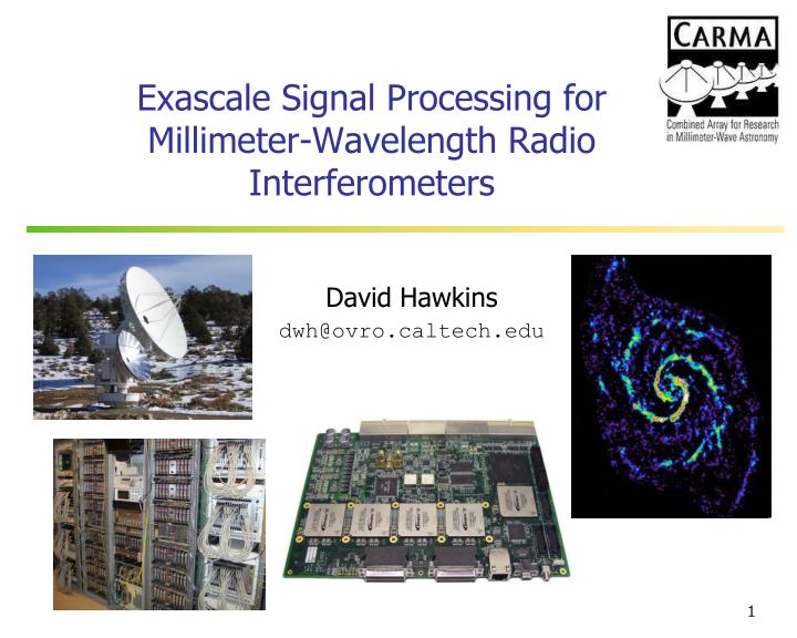
Exascale Signal Processing for Millimeter-Wavelength Radio Interferometers. David Hawkins dwh@ovro.caltech.edu. My Ulterior Motive. I don’t want Exascale Problems! I want Exascale Solutions! Seriously …

E N D
Exascale Signal Processing for Millimeter-Wavelength Radio Interferometers David Hawkins dwh@ovro.caltech.edu
My Ulterior Motive • I don’t want Exascale Problems! • I want Exascale Solutions! • Seriously … • I’m interested in helping test/deploy any hardware that can be integrated with our systems • I’m all for re-using/re-purposing solutions • Larry’s ASICs - version 1.0 coming soon, right? • Mike’s GPUs
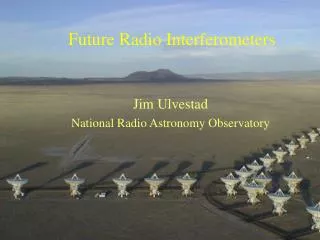
What Systems? (at the Owens Valley Radio Observatory) CARMA • 23 Dual-Polarization Antenna • 30GHz, 100GHz, 300GHz Signals LWA-OVRO • 256 Dual-Polarization Dipoles • 28MHz to 88MHz Signals 3
CARMA’s “Big Data” Problem • CARMA • 23 dual-polarization antennas • 1035 baselines • Current requirements: (not yet met!) • Double-sideband receivers • 8GHz receiver IF (processed as 1 x 10GHz band) • 2-pol x 23-ant x 10GHz = 460GHz bandwidth • 46 x 4-bit x 20GHz ADCs= 3680Tbps (460GB/s) • 368 x 10Gbps links = 92 x 40Gbps links • 46 x 4-bit 20GHz ADCs • “Coming soon”: • Sideband-separating receivers • 16GHz per sideband (processed as 2 x 10GHz bands) • 2-sb x 2-bands x 2-pol x 23-ant x 10GHz = 1840GHz BW • 4 x 3680Tbps = 14720Tbps (1840GB/s) • 4 x 92 = 368 40Gbps links • 184 x 4-bit 20GHz ADCs
Double-Sideband vs Sideband-Separating Sideband-separating removes the sky noise, but produces twice as many analog signals
Need at least 16x larger backend!! 2GHz 23-antenna Single-Polarization Spectral Correlator Wideband Correlator 8 bands x 15-telescopes single-pol 4 bands x 23-telescopes single-pol 4 bands x 15-telescopes dual-pol 16 bands x 8-telescopes single-pol x fixed 500MHz bandwidth
20GHz ADC Prototype #1 • 4-bits at 20Gbps ADC • 8-bits at 10Gbps output data • Tested at 10GSps • 8-bits at 5Gbps to the FPGA • ADC performance verified • ADC-to-FPGA synchronization issue (eventual data corruption) • New board with “more features” required to isolate the issue
ADC-to-FPGA Transceiver Interface Output data modulation is required for lane synchronization and zero bias The 10Gbps lanes are NOT as “simple” as 10GbE links!
Hittite ADC XOR Modulation • XOR input setup/hold • 100ps period XOR pattern • Must meet setup/hold of the 20GHz clock • How can such a stable XOR pattern be generated? • Use a 10GbE PHY configured in PRBS pattern mode! (PRBS = pseudo-random binary sequence)
20GHz ADC Prototype #2 • 20GHz clock, 10Gbps output • 10GHz clock, 5Gbps output • PRBS pattern generator integrated on the PCB • On-board power supplies and output data fanout/buffering isolates the ADC • FPGA independent • Currently being tested • Solder on the ADC pads
Receiver Signal Processing • 10GHz band • Input data rate = 8 x 10Gbps • Output data rate = 32 x 2.5Gbps (higher once encoded) • Overlapped bands allows • Full coarse frequency coverage • High-resolution spectral bands(FFX correlator)
LWA-OVRO (Future) ADC Evaluation 28MHz to 88MHz • Option 1: • ~200MHz sample rate • 8192-point FFT (100MHz/4096-channels = 24kHz resolution) • Retain 28MHz to 88MHz channels (2458 channels) • Option 2: • 256MHz sample rate • Demodulate to complex-valued baseband • Decimate-by-4 (RFI channels eliminated) • 2048-point FFT (64MHz/2048-channels = 31kHz resolution) • Which is better? => To be determined • Option 1 requires a full-precision FFT to retain RFI dynamic range • Option 2 can re-quantize to fewer bits after RFI removal
PFB Low-pass Filter Design Low-pass with sinc “ringing” Kaiser Windowed Response
Summary • What’s next? • New 20GHz ADC boards to test next week • Confirm that PRBS modulation works! • 10GHz PFB implementation • Build-out CARMA’s double-sideband system • 46 x ADCs • Filter using FPGAs • Correlate using FPGAs • CARMA sideband-separating system • Get a lot more ADCs! • Re-use the Correlator FPGAs as Filter FPGAs • Replace the correlator with Larry’s ASICs or Mikes GPUs???