Download
1 / 42
440 likes | 463 Views
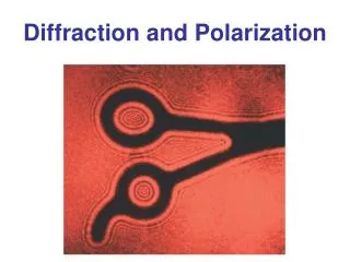
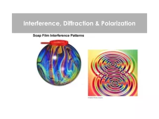
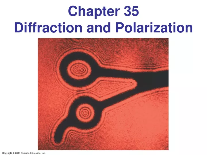
Chapter 35 Diffraction and Polarization. 35-1 Diffraction by a Single Slit or Disk. If light is a wave, it will diffract around a single slit or obstacle. 35-1 Diffraction by a Single Slit or Disk. The resulting pattern of light and dark stripes is called a diffraction pattern.

E N D
35-1 Diffraction by a Single Slit or Disk If light is a wave, it will diffract around a single slit or obstacle.
35-1 Diffraction by a Single Slit or Disk The resulting pattern of light and dark stripes is called a diffraction pattern.
35-1 Diffraction by a Single Slit or Disk This pattern arises because different points along a slit create wavelets that interfere with each other just as a double slit would.
35-1 Diffraction by a Single Slit or Disk The minima of the single-slit diffraction pattern occur when
35-1 Diffraction by a Single Slit or Disk Example 35-1: Single-slit diffraction maximum. Light of wavelength 750 nm passes through a slit 1.0 x 10⁻³ mm wide. How wide is the central maximum (a) in degrees, and (b) in centimeters, on a screen 20 cm away?
ConcepTest 35.1aDiffraction I 1) narrow the slit 2) widen the slit 3) enlarge the screen 4) close off the slit The diffraction pattern below arises from a single slit. If we would like to sharpen the pattern, i.e., make the central bright spot narrower, what should we do to the slit width?
q d q ConcepTest 35.1aDiffraction I 1) narrow the slit 2) widen the slit 3) enlarge the screen 4) close off the slit The diffraction pattern below arises from a single slit. If we would like to sharpen the pattern, i.e., make the central bright spot narrower, what should we do to the slit width? The angle at which one finds the first minimum is: The central bright spot can be narrowed by having a smaller angle. This in turn is accomplished by widening the slit. sin = /d
35-2 Intensity in Single-Slit Diffraction Pattern Light passing through a single slit can be divided into a series of narrower strips; each contributes the same amplitude to the total intensity on the screen, but the phases differ due to the differing path lengths: .
35-2 Intensity in Single-Slit Diffraction Pattern Phasor diagrams give us the intensity as a function of angle.
35-2 Intensity in Single-Slit Diffraction Pattern Taking the limit as the width becomes infinitesimally small gives the field as a function of angle:
35-2 Intensity in Single-Slit Diffraction Pattern . Finally, we have the phase difference and the intensity as a function of angle: and
35-2 Intensity in Single-Slit Diffraction Pattern Example 35-3: Intensity at secondary maxima. Estimate the intensities of the first two secondary maxima to either side of the central maximum.
35-3 Diffraction in the Double-Slit Experiment The double-slit experiment also exhibits diffraction effects, as the slits have a finite width. This means the amplitude at an angle θ will be modified by the same factor as in the single-slit experiment: The intensity is, as usual, proportional to the square of the field.
35-3 Diffraction in the Double-Slit Experiment The diffraction factor (depends on β) appears as an “envelope” modifying the more rapidly varying interference factor (depends on δ).
35-3 Diffraction in the Double-Slit Experiment Example 35-4: Diffraction plus interference. Show why the central diffraction peak shown, plotted for the case where d = 6D = 60λ, contains 11 interference fringes.
35-4 Limits of Resolution; Circular Apertures Resolution is the distance at which a lens can barely distinguish two separate objects. Resolution is limited by aberrations and by diffraction. Aberrations can be minimized, but diffraction is unavoidable; it is due to the size of the lens compared to the wavelength of the light.
35-4 Limits of Resolution; Circular Apertures For a circular aperture of diameter D, the central maximum has an angular width:
35-4 Limits of Resolution; Circular Apertures The Rayleigh criterion states that two images are just resolvable when the center of one peak is over the first minimum of the other.
35-4 Limits of Resolution; Circular Apertures Example 35-5: Hubble Space Telescope. The Hubble Space Telescope (HST) is a reflecting telescope that was placed in orbit above the Earth’s atmosphere, so its resolution would not be limited by turbulence in the atmosphere. Its objective diameter is 2.4 m. For visible light, say λ = 550 nm, estimate the improvement in resolution the Hubble offers over Earth-bound telescopes, which are limited in resolution by movement of the Earth’s atmosphere to about half an arc second. (Each degree is divided into 60 minutes each containing 60 seconds, so 1° = 3600 arc seconds.)
35-4 Limits of Resolution; Circular Apertures Example 35-6: Eye resolution. You are in an airplane at an altitude of 10,000 m. If you look down at the ground, estimate the minimum separation s between objects that you could distinguish. Could you count cars in a parking lot? Consider only diffraction, and assume your pupil is about 3.0 mm in diameter and λ = 550 nm.
35-5 Resolution of Telescopes and Microscopes; the λLimit For telescopes, the resolution limit is as we have defined it: For microscopes, assuming the object is at the focal point, the resolving power is given by
35-5 Resolution of Telescopes and Microscopes; the λLimit Example 35-7: Telescope resolution (radio wave vs. visible light). What is the theoretical minimum angular separation of two stars that can just be resolved by (a) the 200-inch telescope on Palomar Mountain; and (b) the Arecibo radio telescope, whose diameter is 300 m and whose radius of curvature is also 300 m. Assume λ = 550 nm for the visible-light telescope in part (a), and λ = 4 cm (the shortest wavelength at which the radio telescope has been operated) in part (b).
35-5 Resolution of Telescopes and Microscopes; the λLimit Typically, the focal length of a microscope lens is half its diameter, which shows that it is not possible to resolve details smaller than the wavelength being used:
35-6 Resolution of the Human Eye and Useful Magnification The human eye can resolve objects that are about 1 cm apart at a distance of 20 m, or 0.1 mm apart at the near point. This limits the useful magnification of a light microscope to about 500x–1000x.
35-7 Diffraction Grating A diffraction grating consists of a large number of equally spaced narrow slits or lines. A transmission grating has slits, while a reflection grating has lines that reflect light. The more lines or slits there are, the narrower the peaks.
35-7 Diffraction Grating The maxima of the diffraction pattern are defined by
35-7 Diffraction Grating Example 35-8: Diffraction grating: lines. Determine the angular positions of the first- and second-order maxima for light of wavelength 400 nm and 700 nm incident on a grating containing 10,000 lines/cm.
35-8 The Spectrometer and Spectroscopy A spectrometer makes accurate measurements of wavelengths using a diffraction grating or prism.
35-8 The Spectrometer and Spectroscopy The wavelength can be determined to high accuracy by measuring the angle at which the light is diffracted:
35-8 The Spectrometer and Spectroscopy Atoms and molecules can be identified when they are in a thin gas through their characteristic emission lines.
35-8 The Spectrometer and Spectroscopy Example 35-11: Hydrogen spectrum. Light emitted by hot hydrogen gas is observed with a spectroscope using a diffraction grating having 1.00 x 10⁴ lines/cm. The spectral lines nearest to the center (0°) are a violet line at 24.2°, a blue line at 25.7°, a blue-green line at 29.1°, and a red line at 41.0° from the center. What are the wavelengths of these spectral lines of hydrogen?
35-9 Peak Widths and Resolving Power for a Diffraction Grating These two sets of diagrams show the phasor relationships at the central maximum and at the first minimum for gratings of two and six slits.
35-9 Peak Widths and Resolving Power for a Diffraction Grating As the number of slits becomes large, the width of the central maximum becomes very narrow: The resolving power of a diffraction grating is the minimum difference between wavelengths that can be distinguished:
35-9 Peak Widths and Resolving Power for a Diffraction Grating Example 35-12: Resolving two close lines. Yellow sodium light, which consists of two wavelengths, λ1 = 589.00 nm and λ2 = 589.59 nm, falls on a diffraction grating with 7500 lines/cm. Determine (a) the maximum order m that will be present for sodium light, and (b) the width of grating necessary to resolve the two sodium lines.
35-10 X-Rays and X-Ray Diffraction The wavelengths of X-rays are very short. Diffraction experiments are impossible to do with conventional diffraction gratings. Crystals have spacing between their layers that is ideal for diffracting X-rays.
35-10 X-Rays and X-Ray Diffraction X-ray diffraction is now used to study the internal structure of crystals; this is how the helical structure of DNA was determined.
Summary of Chapter 35 • Light bends around obstacles and openings in its path, yielding diffraction patterns. • Light passing through a narrow slit will produce a central bright maximum of width • Minima occur at
Summary of Chapter 35 • Diffraction limits the resolution of images. • Diffraction grating has many parallel slits or lines; peaks of constructive interference are given by • Polarized light has its electric field vectors in a single plane.
Summary of Chapter 35 • The intensity of plane-polarized light is reduced after it passes through another polarizer: • Light can also be polarized by reflection; it is completely polarized when the reflection angle is the polarization angle:
ConcepTest 35.2Diffraction Disk 1) darker than the rest of the shadow 2) a bright spot 3) bright or dark, depending on the wavelength 4) bright or dark, depending on the distance to the screen Imagine holding a circular disk in a beam of monochromatic light. If diffraction occurs at the edge of the disk, the center of the shadow is
ConcepTest 35.2Diffraction Disk 1) darker than the rest of the shadow 2) a bright spot 3) bright or dark, depending on the wavelength 4) bright or dark, depending on the distance to the screen Imagine holding a circular disk in a beam of monochromatic light. If diffraction occurs at the edge of the disk, the center of the shadow is: By symmetry, all of the waves coming from the edge of the disk interfereconstructively in the middle because they are all in phase and they all travel the same distance to the screen. Follow-up:What if the disk is oval and not circular?