Download
1 / 10
100 likes | 507 Views
DATA FLOW DIAGRAMS. An Example. DFD 0: Registration System (Context Level). printer. Registration System (A Toy Example). user. P2 Prepare invoice. P4 Print invoice. invoice. invoice_prt. registration. reg+. reg-profile. P1 Read & check reg. prices. registration db.

E N D
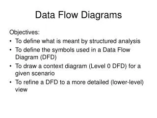
DATA FLOW DIAGRAMS An Example
DFD 0: Registration System (Context Level) printer Registration System (A Toy Example) user P2 Prepare invoice P4 Print invoice invoice invoice_prt registration reg+ reg-profile P1 Read & check reg. prices registration db conf_msg reg_info reg+ P5 Write conf. P3 Accept reg. conf. user
DFD L1: Registration System printer user P2 Prepare invoice P4 Print invoice invoice invoice_prt registration reg+ reg-profile P1 Read & check reg. prices registration db conf_msg reg_info reg+ P5 Write conf. P3 Accept reg. error_msg (reg-) conf. user
DFD L2: P1- Read and Check Registration registration reg+ P1.1 Read registration reg_i P1.2 Check registration reg+ error_reason P1.3 Error-handler registration error_msg (reg-)
Remember during Composition • a process should not have identical inputs and outputs • all data flows must be labelled • sources / sinks are not processes (=active) • data stores should not be connected directly to sources / sinks • there is no timing in a DFD
Suggestions for a Good Style • organise diagram from left to right or top to bottom • provide input and output “filters” for each major data flow • keep sources / sinks on the left or right boundary of your diagram
Process DecompositionInterface Consistency o1 P1 i1 i11 o1 f1 p11 i1 p13 f2 i12 f5 f4 p12 local-data i2 f3 i2
Process Decomposition • processes can be decomposed / refined • one process ===> complete DFD • interface flows must remain consistent • lower level processes, data flows and data stores can be added on • sources sinks remain on level-1 • a level-0 can be used as “abstract”=> Context Level DFD
End of Section 2c coming up: data dictionaries