Download
1 / 60
1.45k likes | 2.47k Views
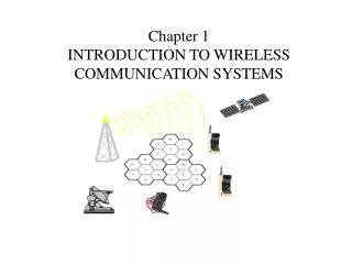
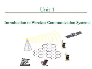
COMMUNICATION SYSTEM EECB353 Chapter 1 INTRODUCTION TO COMMUNICATION SYSTEMS. Dept of Electrical Engineering Universiti Tenaga Nasional. INTRODUCTION TO COMMUNICATION SYSTEMS. Chapter Outline: 1.1 The Block Diagram of Communication System - Definition - Main Components

E N D
COMMUNICATION SYSTEM EECB353Chapter 1INTRODUCTION TO COMMUNICATION SYSTEMS Dept of Electrical Engineering UniversitiTenagaNasional
INTRODUCTION TO COMMUNICATION SYSTEMS • Chapter Outline: • 1.1 The Block Diagram of Communication System - Definition - Main Components - Mode of Communication • 1.2 SNR, Bandwidth & Rate of Communication • 1.3 The Electromagnetic Frequency Spectrum • 1.4 Modulation - Continuous-wave Modulation • - Pulse Modulation • Reference: • Frenzel, Chapter 1
“How do you want to send data/information to someone who is far from you?”
COMMUNICATION OVER LONG DISTANCES IS NO LONGER A PROBLEM. Communication : To transfer information from one place to another
Communication System History • 1837 – Samuel Morse invented telegraph. • 1858 – First telegraph cable across Atlantic (Canada – Ireland) • 1876 – Alexander Graham Bell invented telephone. • 1988 – Heinrich Hertz introduce electromagnetic field theory. • 1897 – Marconi invented wireless telegraph. • 1906 – Radio communication system was invented. • 1923 – Television was invented. • 1938 – Radar and microwave system was invented for World War II. • 1950 – TDM was invented. • 1956 – First telephone cable was installed across Atlantic. • 1960 – Laser was invented • 1962 – Satellite communication • 1969 – Internet DARPA • 1970 – Corning Glass invented optical fiber. • 1975 – Digital telephone was introduced. • 1985 – Facsimile machine. • 1988 – Installation of fiber optic cable across Pacific and Atlantic. • 1990 – World Wide Web and Digital Communication. • 1998 – Digital Television. • 2003 – Internet Telephony
The words "tele", "phon", and "graph" are derived from Greek. • Tele – means ‘at a distance’ • Phon – means sound or speech • Graph - means writing or drawing • Therefore, telecommunication means communication at a distance. This can be done through wires called transmission lines or through atmosphere by a radio link. Other examples include: • Telephone – speaking at a distance Television – seeing at a distance Telegraph – writing at a distance
Significance of Human Communication • Communication is the process of exchanging information. • Main barriers are language and distance. • Methods of communication: • Face to face • Signals • Written word (letters) • Electrical innovations: • Telegraph • Telephone • Radio • Television • Internet (computer)
“If the information that you want to send is your voice, how to make sure that what you are saying is understood by your friend?” Receiving end Sending end Transmission channel Basic Parts of a Communication System
1.1 The Block Diagram of Communication System • Definition - Communication is the transmission of information from a source to a user via some communication link. Figure 1: Com Sys Block Diagram
POSSIBLE SCHEMES COMMUNICATIONS SYSTEM ANALOG DATA OR DIGITAL DATA SOURCE ANALOG DATA OR DIGITAL DATA DESTINATION ANALOG DATA OR DIGITAL DATA NUMBER OF POSSIBLE SCHEMES = A D • AAA • AAD • ADA • ADD • DAA • DAD • DDA • DDD A D A D A D A D A D A D
COMMUNICATIONS SYSTEMS EXAMPLES DIGITAL MODEM ANALOG MODEM DIGITAL WAN/LAN (DIGITAL) IP GATEWAY IP GATEWAY ANALOG ANALOG
COMMUNICATIONS SYSTEMS EXAMPLES AAAIR FREE SPACE RADIO STATION ANALOG ANALOG ANALOG DS1 ANALOG ANALOG CODEC CODEC
Figure 2: Analog Vs Digital Signal 1.1 The Block Diagram of Communication System • Main Components of Com Sys: • Input message can be: • Analog – continuous signal i.e value varies continuously eg. human voice, music, temperature reading • Digital – discrete symbol i.e value limit to a finite set eg. data
1.1 The Block Diagram of Communication System Analog Signals • An analog signal is a smoothly and continuously varying voltage or current. Examples are: • Sine wave • Voice • Video (TV) Figure : Analog signals (a) Sine wave “tone.” (b) Voice. (c) Video (TV) signal.
1.1 The Block Diagram of Communication System Digital Signals • Digital signals change in steps or in discrete increments. • Most digital signals use binary or two-state codes. Examples are: • Telegraph (Morse code) • Continuous wave (CW) code • Serial binary code (used in computers)
1.1 The Block Diagram of Communication System Figure: Digital signals (a) Telegraph (Morse code). (b) Continuous-wave (CW) code. (c) Serial binary code.
CHAPTER 1INTRODUCTION TO COMMUNICATION SYSTEMS WHAT IS BASEBAND ? Electrical Waveform Data (nonelectrical) Without any shift in the range of frequencies of the signal The signal is in its original form, not changed by modulation. Baseband is the original information that is to be Sent.
1.1 The Block Diagram of Communication System • (ii) Input Transducer: • A device that converts energy from one form to another. Convert an input signal into an electrical waveform. • Example: microphone converts human voice into electrical signal referred to as the baseband signal or message signal.
1.1 The Block Diagram of Communication System • (iii) Transmitter (Tx): • Modifies or converts the baseband signal into format appropriate for efficient channel of transmission. • Example: If the channel is fiber optic cable, the transmitter converts the baseband signal into light frequency and the transmitted signal is light. • Transmitter also use to reformat/reshape the signal so that the channel will not distort is as much. • Modulation takes place in the transmitter. It involves static variation of amplitude, phase or frequency of the carrier in accordance to a message signal.
1.1 The Block Diagram of Communication System • (iv) Channel: • Physical medium through which the transmitter output is sent. • Divided into 2 basic groups: • Guided Electromagnetic Wave Channel – eg. wire, coaxial cable, optical fiber • Electromagnetic Wave Propagation Channel – eg. Wireless broadcast channel, mobile radio channel, satellite etc. • Introduces distortion, noise and interference – in the channel, transmitted signal is attenuated and distorted. Signal attenuation increase along with the length of channel. • This results in corrupted transmitted signal received by receiver, Rx
Transmission Medium (Guided) • Twisted pair • Unshielded Twisted Pair (UTP) • Shielded Twisted Pair (STP) • Coaxial • Fiber Optic • Waveguide
1.1 The Block Diagram of Communication System • (v) Receiver • Receiver decodes the received signal back to message signal – i.e it attempts to translate the received signal back into the original message signal sent by the source. • Reprocess the signal received from the channel by undoing the signal modification made by transmitter and the channel. • Extract the desired signal from the received signal and convert it to a form that suitable for the output transducer. • Demodulation takes place in the receiver. (vi)Output transducer • Convert electrical signals to its original waveform.
1.1 The Block Diagram of Communication System Transceivers • A transceiveris an electronic unit that incorporates circuits that both send and receive signals. • Examples are: • Telephones • Fax machines • Handheld CB radios • Cell phones • Computer modems
1.1 The Block Diagram of Communication System • 3. Mode of Communication: • Broadcasting • Involves the use of a single powerful transmitter transmit to many receivers. Demodulation takes place in the receiver. • Information-bearing signals flow in one direction • Eg. TV and radio (Simplex) ii. Point to point Communication • Where a communication process takes place over a link between a single transmitter and a receiver. • Information-bearing signals flow in bidirectional, which requires the use of a transmitter and receiver at each end of the link • Eg. Telephone (Full Duplex) and walkie talkie (Half Duplex)
1.2 SNR, Bandwidth & Rate of Communication • 1. Signal to Noise Ratio (SNR): • SNR is defined as the ratio of signal power to noise power. Noise distorts the signal and accumulated along the path. • The dB value is calculated by taking the log of the ratio of the measured or calculated power (PS) wrt a reference power (PN) level. • Commonly referred to as the power ratio form for dB • It is normally measured in Decibel (dB), defined as 10 times the algorithm (to base 10) of the power ratio. • Eg.: SNR of 10, 100 and 1000 correspond to 10, 20, and 30dBs, respectively. • dBm is a dB level using a 1mW reference. • Example - Convert 1mW to dBm SNRdB SNR =
Decibel (Eq. 1) (Eq. 2) (Eq. 3) • decibel is a relative unit of measurement used frequently in electronic communications to describe power gain or loss • Equation 1 is commonly referred to as the power ratio form for dB.
1.2 SNR, Bandwidth & Rate of Communication Example 1 – A receiver produces a noise power of 200mW with no signal. The output level increases to 5 W when a signal is applied. Calculate (S + N)/N as a power ratio and in decibels. Example 2 – A measured value of 10mW will result in what dBm power level? Example 3 - A laser diode outputs +10dBm. Convert this value to (i) watts (ii) dB
1.2 SNR, Bandwidth & Rate of Communication • Bandwidth • Bandwidth is that portion of the electromagnetic spectrum occupied by a signal. • Specifically, bandwidth is the difference between the upper and lower frequency limits of the signal or the equipment operation range. • Figure 1, shows the bandwidth of the voice frequency range from 300 to 3000Hz. The upper frequency is f2 and the lower frequency is f1. The bandwidth, then is BW = f2 – f1 Bandwidth is the frequency range over which equipment operates or that portion of the spectrum occupied by the signal. This is the voice frequency bandwidth.
Chapter 1Introduction to Communication Systems WHAT IS BANDWIDTH ? IT IS THE DIFFERENCE BETWEEN THE HIGHEST FREQUENCIES AND THE LOWEST FREQUENCIES OF THE INPUT SIGNAL FREQUENCIES (fB= 2fm ). The bandwidth of a communication signal bandwidth of the information signal.
1.2 SNR, Bandwidth & Rate of Communication • Bandwidth • Bandwidth of a channel is the range of frequencies that it can transmit with reasonable fidelity. • Bandwidth of an information signal is the difference between the highest and lowest frequencies contained in the information. • Bandwidth of a communication channel is the difference between the highest and lowest frequencies that the channel will allow to pass through it (ie: its pass band). • Data rate proportional to bandwidth
1.2 SNR, Bandwidth & Rate of Communication • Rate of Communication • Rate of information transmission is directly proportional with its bandwidth • Shannon limit for information capacity, C C = B log2 (1 + SNR) = 3.32B log10 (1 + SNR) Where C = information capacity (bps) B = bandwidth (Hz) SNR = signal to noise ratio (no unit)
1.2 SNR, Bandwidth & Rate of Communication Example 4 -The telephone channel has a bandwidth of about 3kHz. Calculate the capacity of a telephone channel that has an SNR of 1023. Example 5 – For a standard telephone circuit with a SNR of 30dB and a bandwidth of 2.7 kHz, determine the Shannon limit for information capacity.
1.3 The Electromagnetic Spectrum • Electromagnetic waves are signals that oscillate; i.e the amplitudes of the electric and magnetic fields vary at a specific rate. • These oscillation may occur at a very low frequency or at an extremely high frequency. • The range of electromagnetic signals encompassing all frequencies is referred to as the electromagnetic spectrum.
1.3 Electromagnetic Frequency Spectrum • Definition of the Electromagnetic Spectrum • The total span of frequencies and corresponding wavelength used in communications systems.
1.3 Electromagnetic Frequency Spectrum • Frequency and Wavelength: Frequency • A signal is located on the frequency spectrum according to its frequency and wavelength. • Frequency is the number of cycles of a repetitive wave that occur in a given period of time. • A cycle consists of two voltage polarity reversals, current reversals, or electromagnetic field oscillations. • Frequency is measured in cycles per second (cps). • The unit of frequency is the hertz (Hz).
1.3 Electromagnetic Frequency Spectrum • Frequency and Wavelength: Wavelength • Wavelength is the distance occupied by one cycle of a wave and is usually expressed in meters. • Wavelength is also the distance traveled by an electromagnetic wave during the time of one cycle. • The wavelength of a signal is represented by the Greek letter lambda (λ).
1.3 Electromagnetic Frequency Spectrum Figure : Frequency and wavelength. (a) One cycle. (b) One wavelength.
1.3 Electromagnetic Frequency Spectrum Frequency and Wavelength: Wavelength Wavelength (λ) = speed of light ÷ frequency Speed of light = 3 × 10⁸ meters/second Therefore: λ= 3 × 10⁸ / f • Example: • What is the wavelength if the frequency is 4MHz? λ= 3 × 10⁸ / 4 MHz = 75 meters (m)
1.3 Electromagnetic Frequency Spectrum Example 6 A signal with a wavelength of 1.5m , what is its frequency? Example 7 A signal travels a distance of 75ft in the time it takes to complete 1 cycle. What is its frequency? (Given 1m = 3.28ft) Example 8 The maximum peaks of an electromagentic wave are separated by a distance of 0.203m. What is the frequency in MHz and GHz?
1.3 Electromagnetic Frequency Spectrum • The purpose of an electronic communications system is to communicate information between two or more locations/stations. • This is accomplished by converting the original information into electromagnetic energy and then transmitting it to one or more received stations where it converted back to its original form. • Electromagnetic energy can propagate as a voltage or current along a metallic wire, as emitted radio waves through free space or as light waves down an optical fiber. • Electromagnetic energy is distributed throughout an almost infinite range of frequencies.
1.3 Electromagnetic Frequency Spectrum • Antenna & Propagation • Electromagnetic waves consists of electric field (E) & magnetic field (H) • Polarization is determined by the E-field, and thus same with antenna’s physical configuration Polarization – the field of the electric field of an electromagnetic wave
1.3 Electromagnetic Frequency Spectrum • Types of radio wave propagation • Ground Wave (Surface Wave) • Radio wave that travels along the earth’s surface. • The propagation is better over water, esp salt water. • Not effective for freq above 2MHz • Reception not affected by daily or seasonal changes. • Application: submarine application
1.3 Electromagnetic Frequency Spectrum • Space Wave • Divided into 2 types direct wave & ground reflected wave • Limited by line of sight (LOS) • Antenna height and earth curvature become important factors
Sky Wave Radiated from the transmitting antenna in direction toward the ionosphere. Skipping the alternate refracting and reflecting of a sky wave signal between the ionosphere and earth’s surface. The ability of the ionosphere to return the radio wave depends on the ion density, frequency of radio wave and angle of transmission. 1.3 Electromagnetic Frequency Spectrum
1.3 Electromagnetic Frequency Spectrum • Antennas • Half Wave Antenna: • The physical length is 1/2 wavelength of the applied frequency. • Typically used for >2 MHz • Dipole Antenna • Straight radiator, typically ½ wavelength long, usually separated at center by insulator and fed by a balanced transmission line.
1.3 Electromagnetic Frequency Spectrum • Antennas • Radiation Pattern diagram indicating the intensity of radiation as a function of direction • Omnidirectional a spherical radiation pattern • Directional concentrating antenna energy in certain directions at the expense lower energy in other directions • Beamwidth Angular separation between the half power points on an antenna’s radiation pattern • Antenna gain How much more power in dB an antenna will radiate in a certain direction with respect to the reference antenna (isotropic point source or dipole)
Monopole Antenna Typically used for <2 MHz Large amount of energy is launched as a ground wave
1.4 Modulation • Modulation is the process of putting information onto a high frequency carrier in a transmitter. • Modulation is important because: • Ease of radiation - related to antenna design & smaller size. Low loss and low dispersion. • Simultaneous transmission of several signals – enables the multiplexing i.e combining multiple signals for tx at the same time over the same carrier. • Classification of modulation process: • Analog modulation- consists of Continuous Wave (CW) modulation and pulse modulation • Digital Modulation- ASK, PSK, FSK