Download
1 / 45
450 likes | 567 Views
WFXT optics: design optimization and development. Giovanni Pareschi. JKCS041:, z = 1.8, Andreon et al., 2009. Acknowledgement. The WFXT optics team at OAB

E N D
WFXT optics: design optimization and development Giovanni Pareschi JKCS041:, z = 1.8, Andreon et al., 2009
Acknowledgement The WFXT optics team at OAB Paolo Conconi, Sergio Campana , ObertoCitterio, Marta Civitani, VincenzoCotroneo , Giovanni Pareschi, Laura Proserpio, GianpieroTagliaferri , Giancarlo Parodi, (BCVProgetti) Thank you to the whole WFXT collaboration for supporting this work and for many useful discussions! • R. Giacconi, A. Ptak, C. Norman – JHU • S. Murray, A. Vikhlinin – CfA • M. Weisskopf, R. Elsner, S. O’Dell, B. Ramsey – NASA/MSFC • S. Borgani, P. Rosati, P. Tozzi – INAF/OATrieste • S. Molendi – INAF/IASF- Milano ASI is supporting the pre-Phase A study in the context of the contract “High Energy Astrophysics Studies” . INAF is also funding the activities with internal resources.
Outline • Introduction the optical design of wide-field X-ray telescopes • Optical design & Optimization of the WFXT mirrors • A few remarks on manufacturing and implementation of the WFXT optics
WFXT payload top level requirements • Number of X-ray optics modules: 3 • Total payload (optics + detectors) mass: 1440 kg
Grasp Grasp = Aeff x FOV measured at 1.5 keV in cm2 deg2 • Grasp measures the speed in which a survey can cover an area of the sky down to a given flux limit. • Better angular resolution results in better efficiency and source identification.
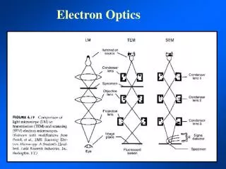
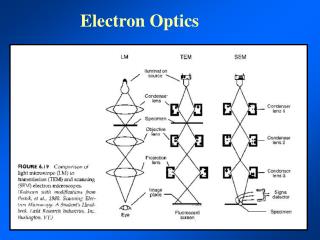
Wolter’s solution to the X-ray imaging H. Wolter, Ann. Der Phys., NY10,94
25’ 20’ 15’ 10’ 5’ 0’ 41’ Wolter I Point SpreadFunction (PSF) ABRIXAS/e-Rosita HEW [arcsec] ABRIXAS “cross scan” calculation Credits: MPE Off-axis angle [arcmin]
R. Giacconi, “AN EDUCATION IN ASTRONOMY”, ARAA. 2005.43: 1- 30, 22 “A further extension of this line of thinking is that experiments could be designed by modelling both the hardware and software as part of the initial design. I myself, together with Richard Burg and Chris Burrows, used this approach in designing in the 1980s what I believe was one of the best experiments I ever conceived. The purpose was to scan the sky and to detect distant clusters of galaxies through their X-ray emission. The idea was that it would be possible to equal or exceed the sensitivity of Chandra with an X-ray telescope of one tenth the area (and cost). This could be achieved by dedicating an entire mission of a small satellite to this purpose and by designing a telescope that would have a >16-fold increase of the field of view with respect to Chandra. ……..”
X-ray optics with polynomial profile: general remarks • Mirrors are usually built in the Wolter I (paraboloid-hyperboloid) configuration which provides, in principle, perfect on-axis images. • This design exhibits no spherical aberration on-axis but suffers from field curvature, coma and astigmatism, • rapid degradation with increasing off-axis angles • More general mirror designs than Wolter's exist • the primary and secondary mirrors are expanded as a power series • Optimization of polynomials • increase the angular resolution at large off-axis positions but degrading the on-axis performances See Burrows, Burgh and Giacconi (1992)
Why short mirror lengths for WFXT • The aspect ratio mirror shell length / focal length plays a very important role; in general the height of the shells should be kept as short as possible • With short mirror shells the spherical aberrationcontribution to the PSF is reduced; moreover a better control of the curvature of the field is achieved • a = on-axisincidence angle • = angular off-set L = mirrorheight F = focallength sphericalabberation coma Van Speybroeck & Chase, Appl. Opt., 1971 • A typical aspect ration between focal length and mirror shell of 14 - 15 must has to be taken (this was for the old WFXT design), but it should change in the interval 10 – 30, depending on the f-number. N.B.: short mirror shells increase of the manufacturing problems!
Optimization of the Single Mirror Shell Best merit function for optimization of surveying telescopes f = Focal Length / Shell Entrance Radius l= (100 x Total Mirror Length / Focal Length) Simplified formula for the HEW of a polynomial optics (BBG, 1992) weighted over the FOV coming from the optimizations (Conconi et al., Applied Optics , 2009, submitted)
Image quality for different f x l products f = 5 ; l = 10 f = 7.1 ; l = 7.1 f = 10 ; l = 5 (Conconi et al., Applied Optics , 2009, submitted)
Polynomial shell (f = 5, l = 7) versus Wolter I and W-S (Conconi et al., Applied Optics , 2009, under submitted)
Aberration Analysis (f = 5, l = 7) (Conconi et al., Applied Optics , 2009, submitted)
Butterfly-like configuration The curvature of the field is dependent on f1.8: In order to maintain the same focal plane curvature, and the same f x l product the length L should change along the series of nested shells. average focal profile internal shell external shell Butterfly-like assembly must be used, with mirror shells shorter at the center. See Conconi and Campana, 2001 – Conconi et al., 2004 - Conconi et al., 2009
Intersection planes at different focal distances • Even if with different height along the series, images produced by different mirror shells do not superimpose exactly, having different plate scales and then they have not the same best focus positions (plate scale problem) • The problem is attenuated by using mirror shells with intersection planes at different positions (i.e. they have to be moved relatively to each-other) See Conconi and Campana, 2001 – Conconi et al., 2004 - Conconi et al., 2009
Shift among the intersection planes 20 arcmin off axis FL = 1 m Outermost and innermost mirror shells The plate scale of the shells is different along the series of nested shells. If not corrected the effect that the focal spots of different shells do not coincide. Correction for 1 m focal length In order to correct the effect a shift among the intersection planes has to be introduced.
Angular resolution optimization strategy • Use of 3-order polynomia (x 2) for optimizing the “parabola” and “hyperbola” • Figure of merit: Effective Area per resolution element • Number of modules: 3 • Diameter: large enough for compliance with requirements effective area maximization
Optimization of the acceptance angle 17 arcim is chosen as acceptance angle for the whole set of shells
Interface with spoke wheels: effects of the axial displacements In order to reduce FEM dimensions only 9 MS have been included in the model. MSs # 1-16-31-46-62 have been modelled with their real characteristics (thickness and material). They have been used for the evaluation of the optical degradation by ray-tracing. In between there are four dummy MSs having mass and stiffness respectively equivalent to the MS groups: from #2 to #15 from #17 to #30 from #32 to #45 from #47 to #61
Mirror modules parameters N.B: the weight was calculated for the full set of shells concerning the 3 mirror modules; at least 30 % more should be accounted for the mechanical structure
Effective area for SiC Coating: Pt + C overcoating
Effective area for Glass Coating: Pt + C overcoating
Why Carbon overcoating? 3 mm wall thickness N.B.: spider vignetting not included
Focal spots at different angular off-sets (1 keV) 0 arcmin 5 arcmin 10 arcmin 20 arcmin 15 arcmin 25 arcmin
Main technical aspects The realization of mirror shells with a small aspect ratio ( length/diameter more than 3-4 times lower than XMM and Chandra) increased difficulty in reaching very good angular resolution: • mechanical behavior closer to a “belt-like” configuration rather than a “tube-like” • border effect errors with a much higher weight in determining the PSF • angular resolution more strongly affected by the slope errors caused by out-of-phase azimuthal errors
Past and future X-ray telescopes:HEW vs. the Mass/Collecting-Area ratio WFXT goal IXO
FEM analysis: short vs. long mirror shells Example: LOADINGS GIVING SMALL SPATIAL SCALE DEFORMED SHAPE (i.e. the deformed shape affects small portion of MS surface (at least in long MS) with strong and local displacement gradients): Loading 5: twelve tangential moments (10Nmm each) applied at front section in 12 point 30° spaced. Loading 6: twelve outward radial forces (0.1N each) applied at front section in 12 point 30° spaced.
Why SiC and Glass for the WFXT mirrors • Higher rigidity mirror shells, based on materials with: • low density (to increase the wall thickness) • good mechanical parameters such as SiC and Glass • can be the solution for the above mentioned problems
WFXT heritage (SiC by epoxy replication) see O. Citterio, et al., ”, SPIE Proc., 3766, 198 (1999) Ghigo et al., SPIE Proc., 3766, 209 (1999) Tests @ Panter-MPE & Marshall XRF WFXT (epoxy replication on SiC) Ø = 60 cm Height = 20 cm F. L. = 300 cm HEW = 10 arcsec @ 0.1 keV Ni replication with same mandrel Ø = 60 cm Height = 20 cm F. L. = 300 cm HEW = 35 arcsec @ 0.28 keV
WFXT goal 9000cm2 WFXT goal 5” Direct polishing approach for WFXT mirror shells Angular resolution Effective area Chandra, Rosat (0.5” – 3”) Direct polishing Direct polishing XMM Newton, Jet X, Swift (15”) Electroformed Ni Electroformed Ni LEGENDA: Technology proved Technology under development Difficult achievement
Materials for carriers • Two materials under investigation: • SiC (CVD for allowing the polishing) • Glass (Fused Silica) Fused Silica Pros SiC CVD Pros • well known material already used in space applications • low density • polishable up to 2 Angstrom (very easy) • outstanding T/M parameters • already used in space applications • low density • polishable up to 2 Angstrom Fused Silica Cons SiC CVD Cons • available just on thick tubes (to be grinded!) • T/M parameters lower than SiC • very hard (long time for polishing) • cost
Mirror shell on astatic support (1) • During metrology and polishing (just for glass and CVC SiC) operations the MS in vertical position (axial gravity) rests on astatic supports, which contrast the gravity by controlled axial forces. • The astatic support number has to be computed in a way that the gravity deflections are sufficiently small.
Direct polishing & metrology Credits: Zeeko, UK Advanced technologies but thy have to be tested on thin shells asap
Glass tube of Heraeus HSQ 300 during grinding Typical working time: 1 week/shell with 1 machine (but it can improve) 60 cm 5 mirror shells already ordered (60 cm diam , 1.5 mm thick; + 4 48 cm diam, 1.5 mm thick). They will be used for direct polishing testing. Credits: Heraeus, Germany
Stress- free CVD SiC material available Credit: TREX, USA 1 mirror shell already ordered ( 30 cm diam; 1.5 mm thick). A secvond (60 cm cm; 1 mm thick) is available from past projects. They will be used for direct polishing testing. Typical deposition time: 100 mm / hour (a couple of days for a shell production)