Download
1 / 5
260 likes | 1.06k Views
L05B: Line defects (dislocations). Two basic types – edge and screw, plus a mixture of these. The edge dislocation can be imagined as being formed by an extra half-plane of atoms inserted into the structure (or removal of half a plane). Note distortion of lattice caused by its presence.

E N D
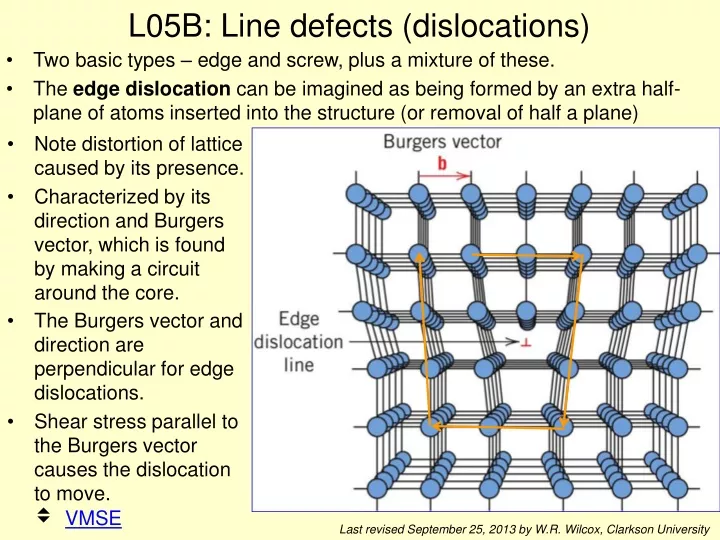
L05B: Line defects (dislocations) • Two basic types – edge and screw, plus a mixture of these. • The edge dislocation can be imagined as being formed by an extra half-plane of atoms inserted into the structure (or removal of half a plane) • Note distortion of lattice caused by its presence. • Characterized by its direction and Burgers vector, which is found by making a circuit around the core. • The Burgers vector and direction are perpendicular for edge dislocations. • Shear stress parallel to the Burgers vector causes the dislocation to move. VMSE Last revised September 25, 2013 by W.R. Wilcox, Clarkson University
Screw dislocations • Can imagine as being formed by cutting half way through the crystal along a plane, and then shifting one part relative to the other in the direction of the cut. • Again, the lattice is distorted near the dislocation core. • Now the Burgers vector isparallel to the dislocation. • Again, shear stress parallel tothe Burgers vector causesthe dislocation to move through the crystal. VMSE Dislocation Burgers vector b
Mixed Edge Screw Edge, Screw, and Mixed Dislocations VMSE Notice that the Burgers vector does not change along the dislocation
Dislocations in non-metals • Much more complex because of covalent and ionic bonding. • If the unit cell is large, then the Burgers vector is also large. • Often carry an electric charge, which can depend on impurity doping. • Example of one model for a <110> edge dislocation in silicon: http://www.ornl.gov/info/ornlreview/v30n3-4/edge.htm
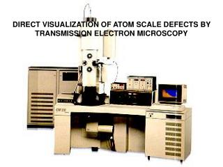
Observation of dislocations • Many methods have been used to observe dislocations, either directly or indirectly. • Most rely on observation of the strain fieldaround the dislocation core. • For example, transmission electron microscopy • X-ray topography (using Brookhaven synchrotron “light source” Clarkson grad student observed dislocation motion in GaAs.) • Transmission optical microscopy using crossed polarizers for ceramic crystals. • “Decoration” of dislocations by impurities. • Etch pits where dislocations emerge on surface. • Growth spirals where screw dislocations emerge on surfaces. (0001) face of carborundum (SiC)