Download
1 / 43
440 likes | 681 Views
Inductors and Chokes In Switch mode Supplies. Thach, Hung 12/06/03 EE136. TERMS. Inductors – is reserved for wound components which DO NOT carry DC current. Chokes – will be used for wound components that carry a large DC bias current, with relatively small ac ripple current. .

E N D
Inductors and Chokes In Switch mode Supplies Thach, Hung 12/06/03 EE136
TERMS • Inductors – is reserved for wound components which DO NOT carry DC current. • Chokes – will be used for wound components that carry a large DC bias current, with relatively small ac ripple current.
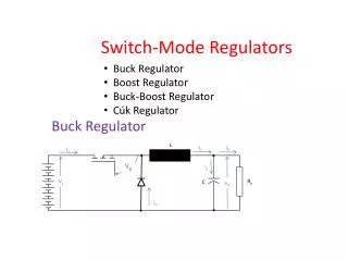
Design Approach • It will depend on the application. • It is often a compromise, with emphasis being placed on: • 1) Minimum cost • 2) Minimum size • 3) Minimum loss
Switch Mode Classification(Inductors) • Inductors will normally be confined to low pass filters. • Their function is to prevent the conduction of high frequency noise back into the supply lines. • For this application, high core permeability would be an advantage.
Chokes • They will be found in high frequency power output filters and continuous-mode buck boost converter “transformers.” • In these applications, low permeability and a low high-frequency core loss would be normally be considered an advantage.
Problems • To minimize the number of turns and copper loss, it might be assumed that a high-permeability core material with a low core loss would be the most desirable. • In choke design, the large DC current component and the limited saturation flux density of real magnetic materials force the selection of a low-permeability material or introduction of an air gap in the core.
As a result of low effective permeability, more turns are needed to obtain the required inductance. • So, in choke design, the desired low copper and high efficiency are compromised by the need to support a large DC current.
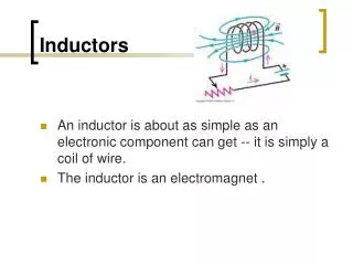
Simple Inductors • In power supply applications, pure inductors (those which do not carry a DC component or a forced high-current ac component) are rare. • The design of these inductors is relatively easy (the inductance may be obtained by the AL value provided for the core, because no gap is required. • L = N² X AL
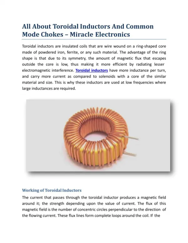
Common-Mode Line Filter Inductors • Common-mode filter inductors have two isolated windings with the same number of turns. • The 2 windings are connected so that the magnetic field that results from normal series-mode ac supply currents will cancel to zero. • The only inductance presented will be leakage inductance between the two windings. • The low-frequency line current will not saturate the core, and a high permeability material may be used without the need for a core air gap. • Large Inductance can be obtained with a few turns.
For common-mode noise (noise currents or voltages which appear on both lines at the same time with respect to the ground), the 2 windings are in parallel and in phase, and a very high inductance is presented to common-mode currents.
Design Example • In this example, it will be assumed that the maximum Common Mode Inductance is required from a specified core size, using a high-permeability ferrite E core. • The effective DC or Low-frequency ac current in the core is zero as a result of using 2 equally opposed and balanced winding. • Core loss is assumed to be negligible because the design is to obtain the maximum possible inductance at the working current from a particular core size.
Core Size • We want to select a core size that suits the mechanical size requirement. • Then calculate the area product (AP). The area product is the product of the core area and the usable winding window area. • Refer to the core area product graph to obtain the thermal resistance of the finished inductor. • AP = ACP X AWb cm^4
Winding Dissipation • Now we need to calculate the permitted winding dissipation W that will give an acceptable temperature rise T. • Then we can obtain the winding resistance Rw at the working (rms) current I. • Assuming zero core loss, W = T / Rth W Rw = W / l² W
From this permitted maximum resistance, the wire gauge, turns, and inductance can be established.
Establishing Wire Size, Turns, and Inductance • Many manufacturers provide information on the resistance and maximum number of turns of a fully wound bobbin using various wire gauges. • The AL factors for the core are often provided, from which the inductance can be calculated. • With balanced windings, there is no need for an air gap.
A nomogram is used to, from which the wire gauge, turns, and resistance of the wound component can be read directly. • An inductor wound following the preceding steps provide the maximum inductance possible on the selected core size, at the maximum rated current and selected temperature rise.
Graphical Design of A Common-Mode-Line-Filter Inductor (using a Ferrite E core)
Assumptions 1) EC35 Core is being used to provide the maximum inductance for a CML filter inductor 2) Temperature rise does not exceed 30°C 3) Input Current is 5 A rms.
Nomogram for establishing wire size for chokes in ferrite material, as a function of turns and core size
The AP of the EC35 is 0.7 (when bobbin is used). • With AP = 0.7, the thermal resistance is 20°C/W. • The dissipation for a temperature rise of 30°C will be : Power = T / Rth = 30 / 20 = 1.5 W
At a Current of 5 A rms, the maximum resistance will be related to power. P = I²R R = 1.5 / 25 = 0.06 W By looking at the 2nd nomogram, you can see that 0.06 W will give you about 56 turns and wire gauge of about 17 (of AWG). Note: In common-mode inductor, the winding will be split into 2 equal parts. Hence, the EC35 bobbin would be wound with 2 windings of 28 turns of #17 AWG
Calculating Inductance (for common-mode inductors wound on Ferrite E cores)
In dual winding, common-mode inductors, the series-mode line frequency or DC magnetization force will cancel out. High permeability core may be used and a core gap is not required. • For the previous example, AL value for the EC35 w/o an air gap is approximately 2000nH. • The inductance for each 28-turn winding can be calculated as follows:
L = N²X AL • For the previous example L = 28²X 2000E-9 = 1.57 mH Note: This graphical design approach also gives the maximum common-mode inductance that can be obtained from this core at 5 A for a temperature rise of 30°C.
CHOKES Inductors with DC Bias Current
Brief Review • Chokes (inductors which carry a large component of DC current). • They are found in some form in all switch mode supplies. • Chokes range from small ferrite beads used, for example, to profile the base drive currents of switching transistors, up to the very large high-current chokes used in power output filters.
Design Considerations • 1) Core Material • 2) Core Design • 3) Core Size • 4) Winding Design Note: Since this subject is very broad, this discussion will be confined to those types of chokes most often used in high-frequency switch mode applications.
Core Material • The Core material is chosen to suit the following conditions: 1) The Operating Frequency 2) Ratio of DC to ac Current 3) Inductance 4) The mechanical requirements
Core Size • Often the most difficult choice is the core size and configuration. • There are many different core topologies that exist, so it may be difficult to decide which would be the optimum choice for a particular application. • The Area Product (AP) tends to be a reasonable constant for all core topologies of the same general power rating, and this can be used for the core size.
Area Product • It is the product of the winding window area and the core center pole area. • In general, AP = Aw * Ac cm ^ 4
Temperature Rise • The temperature rise of the wound component in free air cooling conditions will depend on the total loss in the wound component and the comment's surface area. • The actual temperature rise, DT, that may be expected from a particular core size AP is given by :
DT = P * Rt • DT – temperature rise, °C • P – the total dissipation, W • Rt – thermal Resistance, °C/W Note: In choke design, the loss P will be mainly copper loss. Core Losses are small in most cases, and may be neglected.
Core Air Gaps • If considerable DC currents flow in the choke, the use of gapped E or C cores may be considered. • Since chokes will normally be required to support the DC component w/o saturation, relatively large air gaps are used, and the effective permeability, irrespective of the material chosen, is usually very low – around 10 and 300
Ferrite material saturates at lower flux density than iron, even when gapped. • To prevent saturation, a large gap must be used in the core, resulting in a lower effective permeability and giving lower inductance. • The higher saturating flux density of iron core permits a smaller gap, giving a larger permeability for the same DC bias conditions; hence inductance is greater, and the ripple current will be smaller.
A further advantage of the gapped E or C core is that the effective permeability can be optimized for the application by adjusting the gap size for the most effective performance.
Conclusion • The core size depends on the total loss and the permitted temperature rise. • The copper loss depends on the DC current, turns, and wire size. • The core loss, and hence the choice of material, depends on the ac volt-seconds that the choke must withstand, that is, the flux density swing DB and the operating frequency.
Design Examples of a Gapped Ferrite E-core Choke Using an Empirical Method
Assumptions • The choke is required to support a large DC current with considerable high-frequency ripple current • A low-core loss material is used • An air gap is required • The maximum core size is defined by the mechanical rather than the ideal electrical needs. Note: Typical applications would be an output filter inductor for a high-frequency forward converter. DC current is 10 A and ripple current does not excced 3 A at 100Khz
1) Select core and bobbin size (as defined by mechanical needs), and completely fill the bobbin with a gauge of wire that will give acceptable Power loss and hence acceptable temperature rise. • 2) Assemble core and bobbin, allowing adequate air gap. • 3) Fit the choke in the power filter position in the supply and observe the choke ripple current waveform.
4) Adjust the air gap under maximum load and input voltage conditions until a minimum ripple current is observed. Note: By this, maximum dynamic inductance has now been obtained.
Presentation Conclusion • This presentation was about mainly designing basic Inductors and a brief explanations about how basic chokes are designed. • I would like to thank Dongsheng Zhou, Ph.D. for giving us the opportunity to learn about something interesting.
References • “Switchmode Power Supply Handbook” 2nd edition authored by Keith Billings published by McGraw Hall. (chapter 3.1)