Download
1 / 11
110 likes | 205 Views
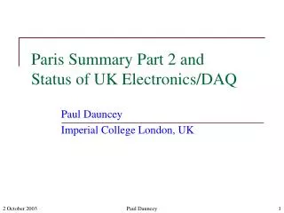
UK Electronics Status. Paul Dauncey Imperial College London. Overview of requirements. Back end electronics for ECAL 30 layers, 1818 pads/layer, total 9720 channels Each channel amplified at front end by VFE chip CR-RC shaper, peaking time ~ 180ns

E N D
UK Electronics Status Paul Dauncey Imperial College London Paul Dauncey - Electronics
Overview of requirements Back end electronics for ECAL • 30 layers, 1818 pads/layer, total 9720 channels • Each channel amplified at front end by VFE chip • CR-RC shaper, peaking time ~180ns • 18 channels/VFE chip, multiplexed analogue output • Need to generate sample-and-hold at peak time • Need to drive multiplex shift register • Need to digitise with 14 bits range, 10 bits precision • Need to send calibration voltage for pulse injection • Need to run at ~100Hz sustained, ~1kHz peak rate • Read out all channels every event for pedestal and noise studies For more details, see: http://www.hep.ph.ic.ac.uk/calice/electronics/electronics.html Paul Dauncey - Electronics
Original proposed system Readout board most complex part • Each cable handled by slave FPGA • Whole board controlled by master FPGA 15 readout boards • Each handles digitisation of 2 layers 1 trigger board • Holds off further triggers until readout complete 1 test board (not shown) • For testing cable connections of readout board Paul Dauncey - Electronics
Conceptual Design Review, 11 Oct CDR was held on 11 Oct at RAL; four external reviewers • Rob Halsall, Adam Baird (RAL), Greg Iles (IC), John Lane (UCL) Technically, design considered good: • Overall concept thought sound and should be kept • Minor issues and suggested improvements (see report) • Cost estimate reasonable But schedule thought unrealistic: • Loss of RAL ID effort since July impacted more than foreseen so schedule further behind than anticipated • RAL drawing office for layout heavily booked (by LHC!) so unlikely to get effort when required N.B. extra three months to Mar 2004 already factored in at CDR Paul Dauncey - Electronics
How to get back on schedule? Rob Halsall and Adam Baird negotiated 1 month RAL ID effort for themselves to work with us up to PPRP approval; they propose • Taking an existing design with similar architecture • Only rework the parts which have to be different • Save layout and engineering effort of rest of board • They will help us evaluate feasibility and resources required Suggest start from CMS Tracker Front End Driver (FED) • Will be used to read out CMS silicon tracker • CMS needs ~500 FEDs in final system • Already taken ~10 man-years of design effort (IC and RAL) • First full-specification prototypes due in Dec 2002 Paul Dauncey - Electronics
PD CMS Tracker FED 5V 3.3V Run/Halt Config E2PROM Id E2 Prom 1.5V 0V 3.3V Compact Flash 1 5V 3.3V 1.5V 1 Test Connector 1 VME LEDs 4x Prog Delay 1 Dual ADC 12x Opto Rx 1 Power Good VME64x Interface FPGA FPGA Synch & Processing Boundary Scan System ACE Buffer Jumper Matrix -5V ASIC Vref 12x trim dac VME FE 1 PD Array 3 6 4x Prog Delay +12V 12 Dual ADC LEDs +5V Temp Sense Front End FPGA +3.3V FPGA Temp Sense Clock Control Data 2.5V 1.5V +2.5V 0V LEDs 2 +1.5V QDR SSRAM -5.0V spare Over temp LEDs TTS TTCrx TTC DAQ ASIC Readout & Synch Control FLT LEDs EMU FSYNC Spare Process Back End FPGA LEDs Transfer VME Temp Sense 43 85 Clock Control Data 22 Readout 4x Prog Delay 3.3V 1.5V Dual ADC 8 Busy 12x Opto Rx 8 LEDs error FPGA halted Synch & Processing ASIC 12x trim dac Vref FE 8 PD Array 24 4x Prog Delay 5.0 V 48 96 E-Fuse Hot swap DC-DC 3.3 V Dual ADC Front End FPGA FPGA 2.5V Temp Sense 1.5V -5.0V extract Hot swap cycle SW Live extract request SW Paul Dauncey - Electronics
5V 3.3V Run/Halt Config E2PROM Id E2 Prom 1.5V 0V 3.3V Compact Flash 1 5V 3.3V 1.5V 1 Test Connector 1 VME LEDs 4x Prog Delay 1 Dual ADC 12x Opto Rx 1 Power Good PD Array VME64x Interface FPGA FPGA Synch & Processing Boundary Scan System ACE Buffer Jumper Matrix -5V ASIC Vref 12x trim dac VME FE 1 3 6 4x Prog Delay +12V 12 Dual ADC LEDs +5V Temp Sense Front End FPGA +3.3V FPGA Temp Sense Clock Control Data 2.5V 1.5V +2.5V 0V LEDs 2 +1.5V QDR SSRAM -5.0V spare Over temp LEDs TTS TTCrx TTC DAQ ASIC Readout & Synch Control FLT LEDs EMU FSYNC Spare Process Back End FPGA LEDs Transfer VME Temp Sense 43 85 Clock Control Data 22 Readout 4x Prog Delay 3.3V 1.5V Dual ADC 8 Busy 12x Opto Rx 8 LEDs error PD Array FPGA halted Synch & Processing 12x trim dac ASIC Vref FE 8 Master BE +VME; very similar 24 4x Prog Delay 5.0 V 48 96 E-Fuse Hot swap DC-DC 3.3 V Dual ADC Front End FPGA FPGA 2.5V PD Temp Sense Slave FE; need to rewrite firmware 1.5V -5.0V extract ADCs, etc; totally different Hot swap cycle SW Live extract request SW FED board compared to readout board Paul Dauncey - Electronics
FED layout Ideally, keep everything to the right, redo everything to the left • Restricts readout board to same I/O and inter-FPGA paths as FED • No show-stopper seen so far Paul Dauncey - Electronics
Other aspects FED is designed to operate in large system for many years • High emphasis on reliability and operation efficiency • Hot swap capability, multiple-level temperature cut-outs, etc. • Way over-engineered for a beam test • May not mount all components to save on cost • FED FPGAs need much greater functionality than readout board • FPGAs are much higher grade (and more expensive) • FED VME FPGA can do VME64; doubles VME data rate FED size is 9U not 6U; cannot reduce without redoing layout • 9U board more expensive; board cost £3k£6k • Bigger, so aim to get more cables per board; 616 • Less boards needed; 156 • 9U crate also more expensive; £5k£10k • Only need one VME crate for whole system Paul Dauncey - Electronics
Trigger and test boards CMS take data out through non-VME backplane pins • Custom data path as VME too slow Unused in readout board implementation • Enough bandwidth to route trigger board signals into BE FPGA • Aim to implement trigger board functions in part of BE • All readout boards will be identical • Select one slot for trigger functions to be turned on • Saves engineering and layout for second PCB • Still need to do firmware Most of FED debugged before used as readout board • Testing much less of an issue • Sophisticated board (£5k plus engineering) considered excessive • Test board will be much simpler, less functional (£1k) Paul Dauncey - Electronics
Cost, effort, schedule Cost needs careful evaluation; probably come out very close • 9U and expensive FPGAs push it up • Less boards and crates pull it down Effort needed from RAL estimated to be slightly higher • Layout effort; 3 months, down from 4 • Engineering effort; 15 months total, up from 12 • Need engineer for duration of project; now goes to Mar 2004 • Would be significantly higher without reusing FED design • Implies underestimate originally, or insufficient progress over summer Scheduleshould fit into later end date of Mar 2004 • Delayed first layout until Apr 2003, after LHC work • Also gives more time for RAL engineer to get up to speed • Reduced prototype test time from 6 to 5 months Paul Dauncey - Electronics