Download
1 / 12
120 likes | 296 Views
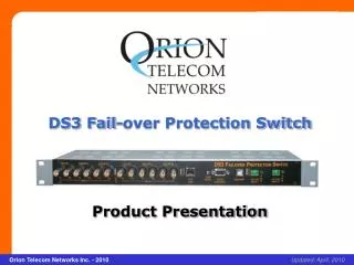
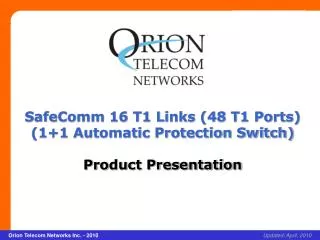
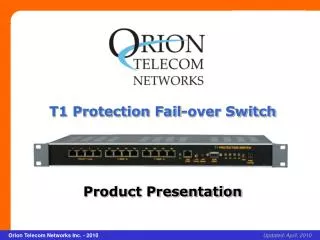
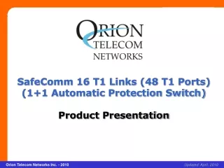
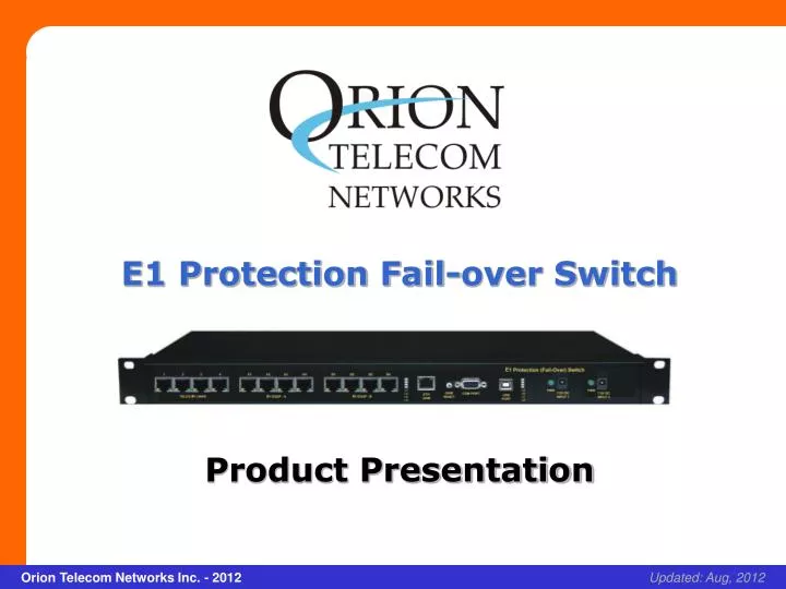
E1 Protection Fail-over Switch Product Presentation. xcvcxv. Orion Telecom Networks Inc. - 2012. Updated: Aug, 2012. Product Overview.

E N D
E1 Protection Fail-over Switch Product Presentation xcvcxv Orion Telecom Networks Inc. - 2012 Updated: Aug, 2012
Product Overview • 12 Port (4 E1 Links) E1 Protection (Fail-Over) Switch allows the user to connect upto four E1 lines from the telephone company to "active", as well as to "standby" E1 terminal(s), such as data server(s), routers etc. at the customer premises. • In the event of the failure of the routers / data server(s) / equipment connected to the "A / active" ports, the E1 Protection (Fail-Over) Switch shall automatically switch and connect the E1 line(s) from the telephone company to the routers /data server(s) / equipment connected to "B / standby" ports. This ensures minimum downtime-that would have otherwise occurred due to equipment failure.
Features: • Allows the users to connect upto 4 E1 lines from the Telephone company to 4 active and 4 standby E1 terminals • User configurable. May be used for a single E1 link and scaled upto 4 E1 links though user configuration • Independent, user configurable switching parameters for each E1 link • Built-in real-time clock / real-time logging maintains a history of all events • Remotely accessible over a TCP/IP networks. Allows the user to access and carry out maintenance, or and E1 switch the links remotely, if required.
Benefits: • Allows the users to create and maintain active/standby/duplicate customer premises data networks/data servers, without requiring to bear the recurring $$$ expense of leasing additional expensive E1s lines from the telephone company • Automatically switches the E1 link(s) from the Telephone Company between the "active" and "standby" E1 equipment at the customer premises, according to the customer-defined criterion • Improves security. Allows the user to co-locate the "backup"/" standby" equipment in a different room/building and prevent data loss • User programmable switching criterion independent for each E1 link • Increases the reliability of the customer data/IT networks without the recurring additional cost of leasing additional E1 lines from the telephone company. • Used to create secondary/backup systems at the customer premises to provide virtually uninterrupted service.
Operations and Maintenance (OAM) Interfaces : • RS232 serial interface for local terminal access • USB serial interfaces for local terminal access • 10/100BaseT Ethernet Interface for remote access over an IP network.
Management and Monitoring: • RS232 serial, USB serial interfaces for local terminal access. • 10/100BaseT Ethernet Interface for remote access over an IP network. • Encrypted Password Protection. • Telnet – Remote access over IP links. • SSH – Secured remote access using Secure Shell Protocol over IP links. • SNMP Traps and NMS for real time remote monitoring and management over an IP network. • Automatic Link Test feature link testing at user programmable periodical intervals. • Visual I/O status LED Display.
User programmable criterion for switching between Active and Standby E1 Links at the customers premises: • Loss of E1 Signal (LOS) • The Loss of Signal condition in a E1 may occur due to: • a) The failure of the E1 Port of the customer premises equipment. • b) Or due to loss of power to the customer premises equipment. • c) Or due to the disconnection of the E1 cable between the protection Switch and the E1 Port of the customer premises equipment. • Loss Of Frame (LOF) This Alarm indicates unframed all ones being detected in the incoming pulses on the receiver of E1 Protection Switch. • Alarm Indication Signal (AIS) This Alarm indicates that the E1 link error has occured.
User programmable criterion for switching between Active and Standby E1 Links at the customers premises: • CRC ERROR • This parameter is the number of CRC-4 errors (Cyclic Redundancy check • errors) that occurred during the test period. • The CRC-4 can be monitored either on-in-service or Out-of-Service E1 • spans. Since the expected value of the CRC pattern can be anticipated, • the received data can be compared to the expected results. Whenever • the expected value does not equal the actual value a CRC error event is • counted. • Switching Time • Change over time from main port to standby port is user configurable from • 10 ms to 3000 ms. • Recovery time from standby to main port is also user configurable from • 10 sec to 1000 sec.
Thank you for your attention For more details visit us at our Website at http://www.oriontelecom.com Headquarters: Phoenix, Arizona Orion Telecom Networks Inc. 16810, Avenue of the Fountains, Suite # 108, Fountain Hills, AZ 85268 U.S.A. Phone: +1 480-816-8672, Fax: +1 480-816-0115 E-mail: sales@oriontelecom.com Website: http://www.oriontelecom.com Regional Office: Miami, Florida Orion Telecom Networks Inc. 4000 Ponce de Leon Blvd. Suite 470, Coral Gables, FL 33146 U.S.A. Phone: 1-305-777-0419, Fax: 1-305-777-0201 E-mail: sales@oriontelecom.com Website: http://www.oriontelecom.com