Download
1 / 47
470 likes | 472 Views
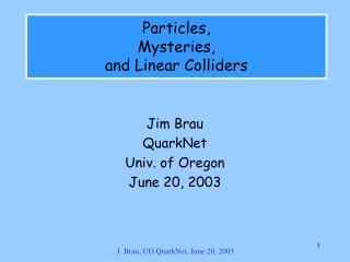
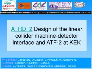
Philip Bambade LAL & KEK On behalf of colleagues from KEK, Saga & Tohoku U., LAL, LAPP and LLR. A_RD_2 Collaboration on ATF2 final focus prototype and MDI for future linear colliders ILC & CLIC. FJPPL’09 Tsukuba May 20-21, 2009. ATF2 final focus test @ KEK.

E N D
Philip Bambade LAL & KEK On behalf of colleagues from KEK, Saga & Tohoku U., LAL, LAPP and LLR A_RD_2Collaboration on ATF2 final focus prototype and MDI for future linear colliders ILC & CLIC FJPPL’09 Tsukuba May 20-21, 2009
ATF2 final focus test @ KEK x = 1.2 nm y~12 (5) pm 1. Expert training on real system 2. Instrumentation for nano-beams 3. Accelerator RD & operation by multi-partner collaboration Goal A : nanometer beam size - obtain y ~ 35 nm at focal point - reproduce reliably y and maintain in time Goal B : trajectory stabilization - 1-2 nm at focal point - intra-train feedback (ILC-like trains) • 2008 end construction & installation • December 2008 first beams • 2009 - 2010 commissioning COST : ~ 3 + 1 M$ Asia, EU, US
ATF2 = scaled version of ILC & CLIC final focus test new local chromaticity correction scheme
LAL LLR Final Doublet mechanical support Integrated vibration evaluation LAPP Beam background study Beam tuning algorithm Commissioning organization KEK Beam tuning algorithm BSM mech. support Infrastructure & support Management
FJPPL contribution to ATF2 (ANR 2006-2010) LAPP:Mechanical support & stability of FD, Commissioning Vibration characterization & modeling in full ATF2 line A. Jérémie, G. Gaillard, N. Geffroy B. Bolzon continued as ANR post-doc LLR:Background evaluation (algorithm, GEANT4) Instrumentation & experimentation for validation M. Verderi, H. Guler (ANR post-doc) LAL:Beam tuning & control, software tools, computing Commissioning strategy & organization P. Bambade, G. Le Meur, C. Rimbault, F. Touze Y. Rénier, M. Alabau (Valencia), S. Bai (IHEP)+ ANR post-doc (2009) KEK:BSM incl. mechanical support, beam tuning strategy Infrastructure, host & direct partner in all activities T. Tauchi, T. Kume, S. Kuroda, T. Okugi, R. Sugahara, J. Urakawa Collaborations: UK, SLAC, CERN, IHEP, Valencia
Present ATF2 status (this slide has been shown unchanged since 2006) • Construction & installation mostly completed end of 2008 • First beam at dump for radiation inspection in Dec. 2008 • Hard- / software commissioning in Feb. & Mar. 2009 • Optical injection match & IP correction in Apr. & May 2009 gradually reducing optical demagnification towards design value
LAPP : Final Doublet supportsmechanical stability & integration
Back to basics : specifications We want the measurement to have a coherent behaviour with respect to the “beam” => Relative motion between Shintake monitor and final doublets:6-7nm in the vertical axis above 0.1Hz Shintake monitor Interference fringes Final doublet With Shintake monitor and final doublet on separate supports with active stabilization coherence is lost Beam Ground 4m Separate stiff supports rigidly fixed to the floor for Shintake monitor and final doublet Good ground motion coherence: measured on KEK site Study the CLIC honeycomb block but without its active feet
Don’t support block on 4 feet fix to floor on entire base Experimental set-up Honeycomb table Bees wax 3 steel plates bolted to the floor No masses: no peak With masses: 92Hz Good boundary conditions chosen for the block: Relative motion should be very low compared to tolerances
Final assembly Quads, sextupoles and movers :SLAC (from FFTB) From floor to mover: LAPP (new) BPM + support: KNU, LAPP IP QD0 SD0 QF1 SF1 Adjustment possible in x, y, z with shims (0.05mm) and adjustment pushers for 1.2m beam height 2.4m Beeswax : good vibration transmission easy to unglue & stable in time & radiation hard Room for slings
QD0FF QF1FF SF1FF SD0FF Sweeping 450.1 450.1 Shintake 200 Honda 200 76.2 180 76.2 180 100 100 100 100 SBPM SBPM SBPM SBPM FFTB 2.13 S3.00 FFTB 2.13 S3.00 QC3 QC3 380 785 380 785 2630 Successfully shipped & installed after detailed mechanical integration design & stability studies done at LAPP Table=2400 IP
Vibration measurements after installation QD0 QF1 Shintake floor (all combinations, with & without water cooling) Sensor Shintake QD0-Shintake : 4.4 nm QF1-Shintake : 6.3 nm Induced beam motion less due to F / D compensation
Vibration measurement along entire ATF2 line update of GM generator parameters • Wave-like motion dominates for f > 0.1 Hz • Modeling possible with 3 waves, both with theoretical expression or using A. Seryi’s ground motion generator Example : fitting propagation velocity from correlation measurements
Application: Combined effect on IP beam of all quad. vibrations Gradual loss of coherence with increasing distance IP beam motion from each quad taking into account its optical lever arm ATF2 final focus functions • Integrated IP beam motion • from final doublet 10 nm • from all quads 14 nm • Lucky compensation between F/D quads and from optical phase advance
LLR : Beam-induced backgroundmeasurements modeling(photons & neutrons)
1. Validate GEANT4 / BDSIM beam line modeling tool with controlled measurements 2. Help minimize background in Shintake monitor Compton photon calorimeter 3. Neutrons and bremstrahlung photons Goals Simulation of beam halo loss along beam line
Use mobile, flexible & modular detector Module (side view) • Scintillator (plastic or CsI) • Photomultiplier Assembly box (top view) • Modules are assembled at will • Radiator slabs (tungstene) can be • inserted at any place • Modules can be assembled off beam in desired configuration • And then carried like a suitcase • Modules for now : • 2 plastic (60×60×38 mm) • 1 CsI (60×60×20 mm) • Acquisition = oscilloscope 45 cm 27 cm Entrance window
Detailed calibrations: mips, neutrons, e-example: cosmic test bench @ lab. • Cosmic bench test used at lab wich records impact points and direction of incident muons. • Allows to measure unbiased mips for PM intercalibation, and absolute calibration wrt simulation. Record (x,y) position of muons Detector box detailed & quantitative background study & prediction for LC + other accelerators Work going on to extract light collection as function of muon impact point on scintillator : measured muon trajectories will be used as input to the simulation to make a per-event estimation of the effect.
LAL : Beam tuning & controlcommissioning strategy & organization
Concept of final focus tuning process bremstrahlung background BSM CAL IP target MATCH EXT DR COL buffer to absorb input variations emittance aperture (aberrations) Gradual demagnification (x,y) reduction paced by progress with : beam tuninginstrumentation (BSM / other) background study
Variable IP at ATF2 nominal value (y = 0.0001m) y [m] April’09 target March’09 target
Extraction line vertical emittance growth ? Could magnets shared with damping ring be the cause of the effect ? Jan’09: QM7 exchanged for larger 42mm bore • Improves but only partial explanation: crucial to reproduce injection orbit
Present commissioning highlights (1) Vertical emittance ~ 20 pm reproduced 3 successive weeks Careful injection orbit setup, dispersion and coupling corrections Automation essential to speed up : 6 skew quads + 5 wire scanners
Present commissioning highlights (2) dd 1) Angular div. & emittance y ~ 1-2 cm close to target value 2) Infer y ~ 0.5 micron at minimum, but measure ~ 2-3 micron betatron match ~ OK but need dispersion & coupling corrections
Software tasks organized at FJPPL ATF2 workshop @ LAL Two environments: V-System & Flight Simulator
Commissioning periods May 2009 3 weeks October – December 2009 7 weeks January – June 2010 14 weeks October – December 2010 7 weeks (extrapolation) Beam time scheduling 50% fraction for ATF2 & 4 days per week operation Individual R&D tasks common goal Groups: KEK, Tokyo, SLAC, IHEP, UK, France, Spain, CERN,… ATF2 educational function Several PhD & young post-doc researchers in accelerator science
Main priorities for 2009-2010 May 2009 8° Shintake interference mode y ~ 0.3 – 2 m reproducible EXT setup y < 40 pm Oct – Dec 2009 174 (or 30) degree mode BSM y ~ 100 nm Jan – Jun 2010 optimization of chromatically corrected tuned beam spot y ~ 40 nm Oct – Dec 2010 reproducibility & stability first go at reduced optics
ATF2 @ PAC’09 (FJPPL contribution) 1. B.Bolzon et al., Linear collider final doublet considerations: ATF2 vibration measurements 2. A.Seryi et al., ATF2 Commissioning 3. R.Tomas et al., ATF2 ultra-low IP betas proposal 4. T.Kume et al., Nanometer stabilization for precision beam size monitor (Shintake monitor) 5. T.Yamanaka et al., Status of the first commissioning of the Shintake monitor for ATF2 6. T.Scarfe et al., ATF2 Spot Size Tuning Using the Rotation Matrix Method 7. R. Apsimon et al., Beam test results with FONT4 ILC prototype intra-train beam feedback system 8. R. Apsimon et al., Development of a Fast Micron-Resolution Beam Position Monitor Signal Processor for Linear Collider Beam-Based Feedback Systems 9. J. Resta-Lopez et al., Design and Performance of Intra-train Feedback Systems at ATF2 10. M. Alabau et al., Study of the effect of the non-linear magnetic fields in the extraction region of the ATF Extraction Line on the emittance growth 11. D.Okamoto et al., Beam orbit tilt monitor studies at ATF2 12. A.Lyapin et al., Development of C-band BPM for ATF2 13. A.Lyapin et al., Development of S-band BPM for ATF2 14. G.White et al., Towards tuning the ATF2 Final Focus System to Obtain a 35nm IP Waist 15. S.Molloy et al., A Flight Simulator based Beam Based Alignment package for ATF2 16. S.Molloy et al., Using the Universal Accelerator Parser to allow the interfacing of third-party accelerator code with the Lucretia Flight Simulator 17. S.Bai et al., Beam waist manipulations at the ATF2 interaction point 18. Y.Renier et al., Orbit rec., correction, stabilization + monitoring in ATF2 extraction line 19. A.Aryshev et al., Micron size laser-wire system at ATF extraction line, recent results inc. ATF2 20. R. Tomas et al., Measurement of non-linear resonances in the ATF DR 21. B. Bolzon et al., LC test facility: ATF2 Final Doublet active stabilization pertinence
Study explores to what extent can be varied the b* Originally motivated to start ATF2 with larger b* values More comfortable situation, less sensitive to errors (non-linear optics…) Study shows that beam size down to ~17 nm might be achievable ! Of large interest for CLIC machine, to demonstrate the its chromaticity regime is feasible Such low b* values are also of interest for alternative (more economical) ILC setups with “pushed” IP parameters Is 37 nm vertical size the limit at ATF2 ?
Study of the block on 4 feet (free-free configuration: 1st peak at 230Hz) Simple simulation (plain block) In the middle of : 0.1Hz-100Hz! • Total relative motion ([0.17; 100]Hz): 6.7nm Above tolerances (6nm)! • Contribution of the peak alone: [10; 100]Hz: 5.7nm • Empty:56.2Hz • with FD weight:26.2Hz Measurements • Empty: 74Hz • With FD weight: 46Hz Can shift to higher frequency if block fixed on entire surface
Simulation tool Develop a simulation application Geant4-based which allows to easily change the detector configuration with macro files. Of course, underneath Geant4 features, as to change the “physics list” for example, are used. Work going on to include PM/scintillator response to further compare with data. ie : no calibration in subsequent plots here Detectors description will be interfaced with BDSIM. Tungstene slabs 100 MeV incoming e- ’s plastic PM & mu-metal CsI Incoming neutrons from Am/Be
Neutron test bench @ Saclay 1 m Detector box Config : plastic; plastic;CsI Polyethylene bricks added to moderate neutron ~40 Hz/cm2 @ 1m Config. : plastic;plastic;CsI Am/Be neutron source 5×10⁶ n/s Interest of Am/Be source : highest neutron energy comparable to that of neutrons from ATF2 beam dump. base line Beware this zone is biaised by trigger ! Full simulation of these data will require to simulate the effect of trigger/threshold.
e+ beam test @ DESY (1/2) We never get individual photon in background measurement @ ATF2 Always get a burst Measuring the energy deposit longitudinal profile may help to get information on photon spectrum To further compare with simulation Sample the profile at: 1X0 : more low E sensitive 4X0 : mostly E insensitive : gets mean energy 10X0 : more high E sensitive Mimic a particle burst by degrading incoming energy with some X0 Simulation g e± Energy spectra after 3X0 for incoming electron
e+ beam test @ DESY (2/2) Detector box 1X0 plastic 3X0 plastic 6X0 CsI With 3X0 in front to degrate incoming energy e+ beam 1,2,3 GeV External trigger Test beam data Simulation Suspect brem. here
Backup Simulation Test beam data
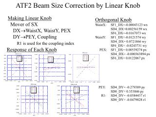
TOKIN 3581 quads available new PRIAM 2D calc. Xext = 22.5 mm • K1L and K2L error almost disappears ! K0L K1L ~ 0.392 m-1 = 0.99 nominal (previously = 0.76 nominal) K2L ~ 1 m-2 (previously = 46.6 m-2) extracted beam offset [m] Radius Turns Max I Current needed: QM7 16mm 17 139 A 130*(42/32)2*17/26= 146 A Q-3581 21mm 26 245 A present PS system sufficient
QM7 PRIAM simulation TOKIN 3581 PRIAM simulation TOKIN 3581 measurement K0L K1L K2L Xextraction 22.5 mm RTOKIN= 21 mm RQM7 =16 mm K1L = 0.99 nominal K2L = 1 m-2 K1L = 0.76 nominal K2L = 47 m-2
Lead block in front of the detector Lead block (5 cm × 3) in front of the detector Most of the fast part was decreased The delayed part was remained
Paraffin shield The delayed background (neutron?) was suppressed after parrafin shield. Concrete shield Paraffin
New “minimal” 2 mrad crossing-angle extraction ILC line concept • Explicit goals : short & economical, as few and feasible magnets as possible, more tolerant and flexible 3 warm bends QF, SF warm quad & sext 2 “Panofsky” quads dump(s): 0.5 m 3 m QD, SD NbTi (Nb3Sn) SC kickers BB1,2 flexible BHEX1 FD Extraction line has been integrated with the FFS collimators | Beam rastering kickers can be placed to prevent water boiling and window damage Length ~ 300 m
QEX1 modified “Panofsky”-style quad design Permanent magnet plates help reduce field to 10 Gauss for incoming beam Multipole expansion QEX1 • Disrupted beam tracking (500 GeV) along the extraction line with multipoles: • Power loss increase of 1kW at 1 collimator • Dump beam size increase of 5% 6m Lumped multipole errors Extra multipole field components modeled in DIMAD


![Samir Arfaoui [CERN/PH-LCD] samir.arfaoui@cern.ch](https://cdn3.slideserve.com/6146196/slide1-dt.jpg)