Download
1 / 30
370 likes | 630 Views
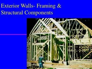
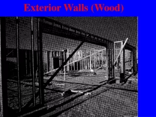
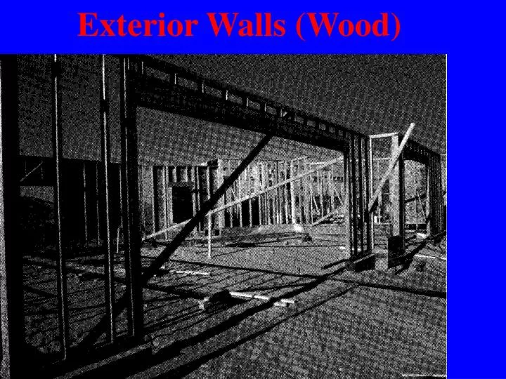
Exterior Walls (Wood). Framing Techniques in Light Frame Construction. General Terms & Methodology Platform Framing Balloon Framing Post & Beam. Wind. Forces on Exterior Wall Construction. Wall had their own dead load Walls support vertical loads (LL + DL) from roof ceiling floors

E N D
Framing Techniques in Light Frame Construction • General Terms & Methodology • Platform Framing • Balloon Framing • Post & Beam
Wind Forces on Exterior Wall Construction • Wall had their own dead load • Walls support vertical loads (LL + DL) from • roof • ceiling • floors • Must also resist lateral forces due to Earthquake (seismic)
Palm tree pierced by plywood missile, Hurricane Andrew Wind--Horizontal/Lateral Load • Wind causes both horizontal & vertical movement with vertical forces called uplift • Use of wind speed map to determine wind speed (70 to 110 miles perhour)
Sucking force Lifting force Wind Forces • Horizontal forces are treated like seismic • Vertical forces are called uplift • Wind blowing across the structure creates a negative pressure (sucking force) • Wind blowing thru an opening increases inside pressure (lifting force)
Earthquakes • Shock waves cause lateral and vertical motion in a building • Usual design, for vertical forces, will take care of the vertical seismic forces • Major factors effecting seismic forces: • The type of structure (material its made of) • Nature of soil under the building • Building are not designed to be earthquake-proof, but to be earthquake resistant
Exposed Earthquake Module Connections called “ductile” are designed to give the building the ability to move, bend or stretch without snap and breaking apart during earthquakes
Typical Wall Construction • One and two story framing • 2” x 4” @ 16” O.C. • Occasionally 2” x 6” @ 24” O.C. • Three story framing(load bearing walls) • lower floor = 2” x 6” @ 16” O.C. • other floors = 2” x 4” @ 16” O.C.
DoublePlate CrippleStuds Header Header Jack Rough Sill Trimmer CrippleStuds Window Framing Terms • Header • supports structure above windows • Header Jack • supports header • Cripple Studs • Double Plate • Rough Sill • Trimmer • additional stud to trim out window
PlatformFraming Rafter or Truss Subfloor is Platform Also called Western Framing Blocking Double Plate Sway Bracing (cornerbracing) Girder Ledger Floor Joist Sill (Mud Sill) Foundation Sheathing
BalloonFraming Studs extend from sill to roof line (full length) Also called Eastern Framing Terms similar to Platform Framing
Balloon Framing • Used primarily for 2 story construction • Less chance of shrinkage or movement • recommended for masonry veneer & stucco • 2nd floor supported by wall with • let-in 1x4 called a ribbon • Less overall material • Longer members usually more costly • Firestop blocking required
Balloon Framing Terms • Ribbon • Firestop
Framing Construction at Corners • 3 full studs • good with super insulated buildings • 3 full studs and blocking • 3 full studs and 1/2” shim
beam T&G planks 2x6 or 2x8 post Post & Beam Relatively new and less common in residential construction Used in heavy timber const for years Beam and Post typically 4’-8’ OC
Tongue & Groove Planking • Used for Roof or Floor when structure is space 24” or more O.C.
Shear Wall Design • Resistance to lateral forces resulting from earthquakes or wind • Connections: • 1 sheathing to joist • 2 joist to top wall • 3 edge nailing • 4 tie-down straps • 5 anchor/shear bolts
Detailing areas of Shear Walls Diaphragm transfer
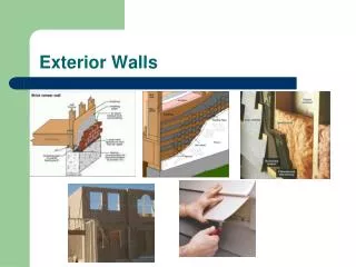
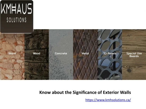
Exterior Finishes • Siding • Wood Siding • Metal Siding • Steel • Aluminum • Vinyl Siding • Stucco • Exterior Finish System--a nylon mesh & plaster over insulation board
Wood Siding • Various sizes and Shapes • Solid wood • T1-11 (plywood) • 4’x8’ sheets • Masonnite Lap board • 8-12” x 16’
Steel & Vinyl Siding • Higher in Cost • Lower in Maintenance • no painting • Long lasting • Concerns when using this siding • expansion • denting • cracking • rusting
Cement Stucco sheathing vs. open frame Least expensive building paper wire fabric lath furring nails drip screed 3 coats of plaster finish }7/8” brown scratch
Interior Finishes • Plaster & Lath • Wood Paneling • Dry wall
Plaster & Lath • Old technique - not in common use today • 3/8” - 1/2” thick lath • 1/2” coat plaster • uses a ground board at edges
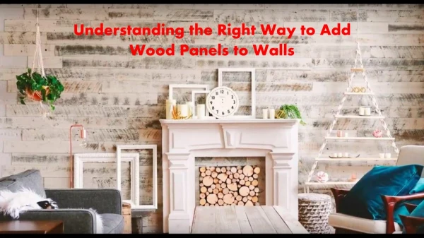
Wood Paneling • 4’ x 8’ sheet panels • vertical/horizontal/angle pieces • solid boards • wide range of wood types and colors
Drywall • Commonly called sheet rock, gypsum board (GB), or plaster board • typically 1/2” on wall, 5/8” on ceiling • Nail directly to studs, nails commonly 8” OC • Tape - 3 coats/ texture • Green/blue board or cement board for bathrooms
Assignment • Sheet A-4 • Dimension the enlarged entry plan • Add restrooms to match A-1 & A-2 • Reference door and window (A-1 & A-2) • Hatch or poche’ as needed • Using elevation 1/A-4 create elevations for A/A-4 and B/A-4
Drawing Assignment Wall Section • 5/8”dia x 12”AB @ 32” • 8” Min from backfill to top FDN • 4” concrete slab w/ 6x6 10/10 wwf or wwm (wire welded fabric or mess) • Blocking • 6-8”compact fill 95% density • foundation wall 8” with normal footing size (w x 2w) 30” frost depth • Foundation insulation
Drawing Assignment Wall Section Cont. • 2”x4” wood studs • Treated wood plate • Found. (2) #5 bars top and bottom and (1) #5 @ 18” o.c. vertical • 12”x18” cont. conc. footing w/ (2) #4 bars x cont. • #4 ties @ 18” o.c. (50% 2’-6” & 50% 1’-6”) • T&G plywood subfloor (second level)
Wall Section Drawing Cont. • Slope 3:12 • 5/8” GB inside wall • Beam bearing @ 8’-0” • Roof beam 3x10 • 3/4” CDX plywood sheathing • 3/4” T1-11 siding (brick, stucco, etc.) • Overhang 18” • 2x2 starter board 1-1/2” from edge