Download
1 / 48
480 likes | 672 Views
Part 1. Transport Layer. Reliable Transport Protocols. Chapter Overview: transport layer services multiplexing/ demultiplexing connectionless transport: UDP principles of reliable data transfer connection-oriented transport: TCP reliable transfer flow control connection management

E N D
Part 1 Transport Layer Reliable Transport Protocols
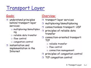
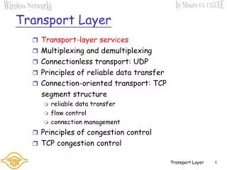
Chapter Overview: transport layer services multiplexing/demultiplexing connectionless transport: UDP principles of reliable data transfer connection-oriented transport: TCP reliable transfer flow control connection management principles of congestion control TCP congestion control Transport Layer Chapter goals: • understand principles behind transport layer services: • multiplexing/demultiplexing • reliable data transfer • flow control • congestion control • instantiation and implementation in the Internet
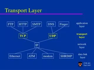
application transport network data link physical network data link physical network data link physical network data link physical network data link physical logical end-end transport network data link physical application transport network data link physical Transport services and protocols • provide logical communication between app’ processes running on different hosts • implemented in end systems, but not in network routers • transport vs network layer services: • network layer: data transfer between end systems • transport layer: data transfer between processes • relies on, enhances, network layer services • Constrained by service model of Network-layer protocol Let’s look at a simple analogy to see their subtle differences
Transport Layer vs. Network Layer An Analogy: Cousins sending letters West Coast East Coast Postal-service mail carrier Uncle Bill Uncle Sam • Uncle Sam & Uncle Bill - responsible for mail collection, distribution, and communicating with postal service • Postal service – carries the mails from house to house
Transport Layer vs. Network Layer hosts (also called end systems) = ? processes = ? application messages = ? network layer protocol= ? transport layer protocol = ?
Transport Layer vs. Network Layer Their services are constrained by the possible services that the postal service provides hosts (also called end systems) = houses processes = cousins application messages = letters in envelope transport layer protocol = Uncle Sam and Uncle Bill network layer protocol= postal service (including mail persons) It may so happen that their uncles could get sick, and so other people may take over – analogously, the computer network may provide multiple transport protocols
Transport Layer vs. Network Layer Transport Layer Network Layer • logical communication between processes • logical communication between end systems • moves messages from application process to the network layer and vice-versa: Sending & Receiving sides • computer network can make multiple transport layer protocols available • TCP • UDP • process-to-process communication • host-to-host communication
Logical Communication sending receiving • receives 4-PDUs • converts messages to 4-PDUs • removes transport header Breaks down application messages into smaller chunks + transport layer header = 4-PDUs • reassembles the messages • passes to receiving application process • Network Layer: Each 4-PDU encapsulated into a 3-PDU
application transport network data link physical network data link physical network data link physical network data link physical network data link physical logical end-end transport network data link physical application transport network data link physical Transport-layer protocols Internet transport services: • reliable, in-order unicast delivery (TCP) • congestion • flow control • connection setup • unreliable (“best-effort”), unordered unicast or multicast delivery: UDP • services not available: • real-time • bandwidth guarantees • reliable multicast Critical Function: Extend IP’s service from host-to-host delivery to process-to-process delivery.
M M application transport network M M application transport network application transport network M H n Multiplexing/demultiplexing Demultiplexing: delivering received segments to correct app layer processes Recall: segment - unit of data exchanged between transport layer entities • aka TPDU: transport protocol data unit receiver P3 P4 application-layer data segment header P1 P2 segment H t segment
Multiplexing: Multiplexing / demultiplexing gathering data from multiple app processes, enveloping data with header (later used for demultiplexing) 32 bits multiplexing/demultiplexing: • based on sender, receiver port numbers, IP addresses • source, dest port #s in each segment • recall: well-known port numbers for specific applications source port # dest port # other header fields application data (message) TCP/UDP segment format Ports: 0-1023 are well-known and restricted, complete list: www.iana.org, RFC 3232
source port: x dest. port: 23 source port:23 dest. port: x Source IP: C Dest IP: B source port: y dest. port: 80 Source IP: C Dest IP: B source port: x dest. port: 80 Source IP: A Dest IP: B source port: x dest. port: 80 Multiplexing/demultiplexing: examples Web client host C server B host A port use: simple telnet app Web server B Web client host A port use: Web server How does a Web Server allow for multiple clients connecting to it at the same time if it’s using TCP?
Why is there a UDP? no connection establishment (which can add delay) simple: no connection state at sender, receiver small segment header no congestion control: UDP can blast away as fast as desired UDP: User Datagram Protocol [RFC 768] TCP – 20 bytes, UDP – 8 bytes • “no frills,” “bare bones” Internet transport protocol • “best effort” service, UDP segments may be: • lost • delivered out of order to app • connectionless: • no handshaking between UDP sender, receiver • each UDP segment handled independently of others Additional functionalities are implemented by the application
UDP: more For segment error checking • often used for streaming multimedia apps • loss tolerant • rate sensitive • other UDP uses (why?): • DNS • SNMP • reliable transfer over UDP: add reliability at application layer • application-specific error recover! 32 bits source port # dest port # Length, in bytes of UDP segment, including header checksum length Application data (message) UDPsegment format
Receiver: compute checksum of received segment check if computed checksum equals checksum field value: NO - error detected YES - no error detected. But maybe errors nonetheless? More later …. Goal: detect “errors” (e.g., flipped bits) in transmitted segment UDP checksum Sender: • treat segment contents as sequence of 16-bit integers • checksum: addition (1’s complement sum) of segment contents • sender puts checksum value into UDP checksum field
The 1’s complement of ‘r’ is: 0011010100110101 at destination, the sum of four packets should be: 1111111111111111 If the packet is damaged: 1111101111111111 (zeros!!) UDP checksum example: • Three packets of 16 bits each • 0110011001100110 • 0101010101010101 • 0000111100001111 • adding the three, calling it ‘r’: • 1100101011001010 • Send the four packets, the original three and 1’s complement of ‘r’ to destination Why provide for error checking? No guarantee that it is provided in all of the links between source and destination
characteristics of unreliable channel will determine complexity of reliable data transfer protocol (rdt) Principles of Reliable data transfer • important in application, transport and link layers • top-10 list of important networking topics!
characteristics of unreliable channel will determine complexity of reliable data transfer protocol (rdt) Principles of Reliable data transfer • important in application, transport and link layers • top-10 list of important networking topics!
rdt_send(): called from above, (e.g., by app.). Pass data to deliver to receiver’s upper layer deliver_data(): called by rdt to deliver data to upper layer rdt_rcv(): called when packet arrives on rcv-side of channel udt_send(): called by rdt, to transfer packet over unreliable channel to receiver Reliable data transfer: getting started send side receive side
Reliable data transfer:getting started state 1 state 2 event actions We’ll: • incrementally develop sender, receiver sides of reliable data transfer protocol (rdt) • consider only unidirectional data transfer • but control info will flow on both directions! • use finite state machines (FSM) to specify sender, receiver actions taken on state transition state: when in this “state” next state uniquely determined by next event
Rdt1.0: reliable transfer over areliable channel • underlying channel perfectly reliable • no bit errors • no loss of packets • separate FSMs for sender, receiver: • sender sends data into underlying channel • receiver read data from underlying channel
Rdt2.0: channelwith bit errors Occurs during transmission, propagation and buffering • underlying channel may flip bits in packet • recall: UDP checksum is used to detect bit errors • the question: how to recover from errors: • acknowledgements (ACKs): receiver explicitly tells sender that pkt received OK • negative acknowledgements (NAKs): receiver explicitly tells sender that pkt had errors • sender retransmits pkt on receipt of NAK • human scenarios: message dictation using ACKs, NAKs? • new mechanisms in rdt2.0 (beyond rdt1.0): • error detection • receiver feedback: control msgs (ACK,NAK) rcvr->sender • retransmission
rdt2.0: FSM specification sender FSM receiver FSM
rdt2.0: in action (error scenario) sender FSM receiver FSM
rdt2.0has a fatal flaw! What happens if ACK/NAK gets corrupted? • sender doesn’t know what happened at receiver! • It can’t just retransmit: there’s a possibility of duplication What to do? • sender ACKs/NAKs receiver’s ACK/NAK? However, what if the sender’s ACK/NAK gets lost? • retransmit, but this might cause retransmission of correctly received pkt! Handling duplicates: • sender adds sequence number to each pkt • sender retransmits current pkt if ACK/NAK garbled • receiver discards (doesn’t deliver up) duplicate pkt stop and wait protocol Sender sends one packet, then waits for receiver’s response
rdt3.0: channelswith bit errors and loss Alternating bit Protocol New assumption:underlying channel can also lose packets (data or ACKs) • checksum, seq. #, ACKs, retransmissions will be of help, but not enough Q:how to deal with loss? • sender waits until certain data or ACK lost, then retransmits • yuck: drawbacks?
rdt3.0 sender Approach: sender waits for a “reasonable” amount of time for an ACK • retransmit if no ACK is received within this period • if pkt (or ACK) just delayed (not lost): • retransmission would cause packet duplication, but use of seq. #’s already handles this • receiver must specify seq # of pkt being ACKed • requires countdown timer Put the burden of detecting and recovering from lost packets to the sender
sender receiver
sender receiver
sender receiver
sender receiver
8kb/pkt T = = 8 microsec transmit 10**9 b/sec 0.008 msec fraction of time sender busy sending = = 0.000267 Utilization = U = 30.008 msec • 1KByte of packet every 30 msec -> 267 kb/secthroughput over 1Gbps link • network protocol limits use of physical resources! Performance of rdt3.0 • rdt3.0 works, but performance is not acceptable • example: 1 Gbps link, 15 msend-to-end propagation delay, 1KByte packet (1KByte = 8Kbit) • Utilization of sender (time busy sending)
Two generic forms of pipelined protocols: Go-Back-NandSelective Repeat Pipelined protocols Pipelining: sender allows multiple, “in-flight”, yet-to-be-acknowledged packets • range of sequence numbers must be defined • buffering at sender and/or receiver
Go-Back-N Sender is allowed to transmit up to NunACKed packets Sender: Uses a window of size N = value that limits the number of outstanding unACKed packets – for Flow control Keeps track of the different sub-intervals in the range of SEQ numbers using: N, base and nextseqnum. base Sequence Number Space Defined in packet header, with k-bit sequence # nextseqnum nextseqnum nextseqnum nextseqnum nextseqnum nextseqnum nextseqnum nextseqnum
Go-Back-N: Sender Receiver: Sender: expectedseqnum++ Sample Run base 0 1 2 3 4 5 6 7 8 9 10 11 12 13 14 15 16 17 18 19 20 21 22 23 24 Initially, base=nextseqnum=8 N=16, base+N =8+16=24 Start timer nextseqnum nextseqnum nextseqnum nextseqnum nextseqnum nextseqnum nextseqnum nextseqnum
Sender must respond to: • Cumulative ACKs: - ACK(n): ACKs all pkts up to, including seq # n - “cumulative ACK” - may receive duplicate ACKs (see receiver) • Rdt_send(): - Before a packet is sent, the Window is checked first if its full; variables: base, nextseqnum and N • Timeout Event: -Timeout(n): retransmit pkt n and all higher seq # pkts in window - Only 1 timer is used: for the oldest transmitted but not yet ACKed packet Go-Back-N: Sender
Go-Back-N: Extended FSM for the Sender rdt_rcv(rcvpkt) && corrupt(rcvpkt)
Go-Back-N: Extended FSM for the Receiver Receiver: • Respond by ACK-only: always send ACK for correctly-received pkt with highest in-order seq # • may generate duplicate ACKs • need only remember expectedseqnum • Discards out-of-order pkts • no receiver buffering! • ACK pkt with highest in-order seq # expectedseqnum++
Go-Back-N in action N=4 Expected sequence num=2
Selective Repeat • Receiver:individually acknowledges all correctly received pkts • buffers pkts, as needed, for eventual in-order delivery to upper layer • Sender: only resends pkts for which ACK was not received • one timer for eachunACKedpkt • Sender Window: • N consecutive Seq #’s • again limits seq #s of sent, unACKedpkts
receiver sender pktn in [rcvbase, rcvbase+N-1] • send ACK(n) • out-of-order: place in buffer • in-order: deliver (also deliver buffered, in-order pkts), advance window to next not-yet-received pkt pktn in [rcvbase-N,rcvbase-1] • ACK(n) otherwise: • ignore Selective Repeat data from above : • Send pkt if seq # is within the sender’s window; otherwise, it is buffered or returned to app. process timeout(n): • resend only a single pktn, then, restart timer ACK(n) in [sendbase, sendbase+N-1]: • mark pktn as received • if n smallest unACKedpkt, advance window base to next unACKedseq #
Selective repeat in action Corrections needed for this slide!
Selective repeat in action x ACK1 rcvd, pkt5 sent 0 1 2 3 4 5 6 7 8 9 Pkt5 rcvd, buffered, ACK5 sent 0 1 2 3 4 5 6 7 8 9 Pkt2 TIMEOUT, pkt2 resent 0 1 2 3 4 5 6 7 8 9 Pkt2 rcvd, pkt2,pkt3,pkt4,pkt5 delivered, ACK2 sent 0 1 2 3 4 5 6 7 8 9 ACK3 rcvd, nothing sent 0 1 2 3 4 5 6 7 8 9
Selective repeat dilemma: retransmission or new packet? Example: • seq #’s: 0, 1, 2, 3 • window size=3 • receiver sees no difference between two scenarios! • incorrectly passes duplicate data as new in (Fig. a) Q: what relationship between seq # size and window size? A window size= (size of Seq # Space-1) won’t work Figurative Curtain
Selective repeat: dilemma Setting the Window Size To account for possible packet duplication due to SEQ # assigning, packets are not allowed to “live” more than 3 min. (TCP Extensions for high speed networks) in the network.