Download
1 / 1
10 likes | 124 Views
Development of electrical models for inductive coils used in wireless power systems Paul Burke Website: www.wirelesspowertransfer.wordpress.com Department of Electrical & Electronic Engineering National University of Ireland Galway, Ireland.

E N D
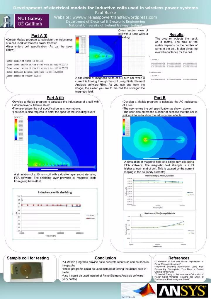
Development of electrical models for inductive coils used in wireless power systems Paul Burke Website: www.wirelesspowertransfer.wordpress.com Department of Electrical & Electronic Engineering National University of Ireland Galway, Ireland Cross section view of coil with 3 turns without shielding Results The program outputs the result as a matrix. The size of the matrix depends on the number of turns in the coil. It also gives the overall inductance for the coil. • Part A (i) • Create Matlab program to calculate the inductance of a coil used for wireless power transfer. • User enters coil specification (As can be seen below). A simulation of magnetic fields of a 3 turn coil when a current is flowing through the coil using Finite Element Analysis software(FEA). As you can see from the image, the closer you are to the coil the stronger the magnetic field. • Part A (ii) • Develop a Matlab program to calculate the inductance of a coil with a double layer substrate shield • The user enters the coil specification as shown above. • The user is also required to enter the spec for the shielding layers • Part B • Develop a Matlab program to calculate the AC resistance of a coil. • The user enters the coil specification as shown above. • The user also enters the number of sections that the coil is split up into so to show the eddy current effects A simulation of magnetic field of a single turn coil using FEA software. The magnetic field strength is a lot higher at each end of coil. This is caused by the current looping in the coil(eddy currents). A simulation of a 10 turn coil with a double layer substrate using FEA software. The shielding layer prevents all magnetic fields from going beneath it. • Conclusion • All Matlab programs provide quite accurate results as can be seen in the graphs • These programs could be used instead of testing the actual coils in the lab • Also it could be used instead of Finite Element Analysis software (very costly) • References • “Calculation of Self and Mutual Impedances in Planar Magnetic Structures” • “Improved Shielding performance Using High Permeability Electroplated Thin Films in Printed Circuit Boards(PCB)” • “Extended Theory on the Inductance Calculation of Planar Spiral Windings Including the Effect of Double-layer Electromagnetic Shield” Sample coil for testing