Download
1 / 46
460 likes | 624 Views
Optical links for the CMS Tracker at CERN. J. Troska (on behalf of Karl Gill) CERN EP Division. Outline. 1. Introduction Project LHC/CMS/Tracker/Optical Links Environment 2: Radiation damage testing at CERN Lasers fibres/connectors photodiodes System considerations 3: Summary

E N D
Optical links for the CMS Tracker at CERN J. Troska (on behalf of Karl Gill) CERN EP Division
Outline • 1. Introduction • Project • LHC/CMS/Tracker/Optical Links • Environment • 2: Radiation damage testing at CERN • Lasers • fibres/connectors • photodiodes • System considerations • 3: Summary • Copies of slides available: http://gill.home.cern.ch/gill/talks.html
LHC at CERN Large Hadron Collider 27 km circumference 7 TeV proton beams CMS CERN, Geneva
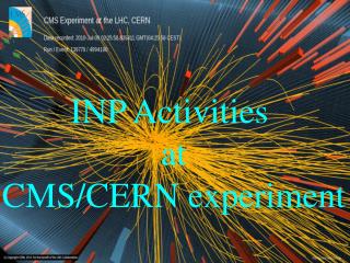
CMS at CERN/LHC • **
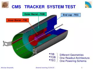
CMS Tracker development Layers of silicon microstrip detectors Barrel layer prototype ~10 million detector channels Forward disk prototype
CMS Tracker analogue optical link • Transmitter - 1310nm InGaAsP EEL • Fibres and connectors - Ge-doped SM fibre • Receivers - InGaAs 12-way p-i-n • plus analogue electronics - rad-hard deep sub-micron
Tracker radiation environment • high collision rate • high energy • large number of tracks • radiation damage • lifetime >10 years • temperature -10C Charged hadron fluence (/cm2 over ~10yrs)
CMS Tracker readout and control links • final system: Analogue Readout 50000 links @ 40MS/s Parts under test for radiation damage FED Detector Hybrid Tx Hybrid 96 Rx Hybrid processing MUX A buffering APV 4 DAQ 2:1 D amplifiers 12 12 C pipelines 128:1 MUX PLL Delay Timing DCU TTCRx TTC Digital Control 2000 links @40MHz FEC Control 64 4 TTCRx CCU CCU 8 processing buffering CCU CCU Back-End Front-End
Environments • Optoelectronics already employed in variety of harsh radiation environments • e.g. civil nuclear and space applications Total dose (Gy) 1E+8 Space (p,e) Nuclear (g, also n) 1E+6 CMS TK 1E+4 1E+2 CMS cavern 1E+0 1E-2 1E-2 1E+0 1E+2 1E+4 1E+6 Dose rate (Gy/hr)
COTS issues • Extensive use of commercial off-the-shelf components (COTS) in CMS optical links • Benefit from latest industrial developments • cheaper • “reliable” tested devices • However COTS not made for CMS environment • no guarantees of long-life inside CMS • validation testing of COTS mandatory before integration into CMS
COTS components for CMS Tracker links • Some examples: 96-way cable 1-way InGaAsP edge-emitting lasers on Si-submount with ceramic lid 12-way optical ribbon and MT-connector single fibre and MU connector
Validation procedures for rad-resistance • E.g. lasers and photodiodes Highlighted: 1999 Market survey validation tests (in-system) lab tests girradiation pirradiation ageing nirradiation annealing (in-system) lab tests • Feedback test results into system specifications • radiation damage effects can then be mitigated
Neutron tests at UC Louvain-La-Neuve Recent validation tests of laser diodes ~20MeV neutrons flux ~ 5x10¹⁰n/cm2/s fluence ~ 5x10¹⁴n/cm2 (Similar to CMS Tracker 10 year exposure) deuterons neutrons Samples stacked inside cold box (-10C) neutrons
Radiation test system • Test setup for in-situ measurements • In-situ measurements give powerful capability to extrapolate damage effects to other radiation environments • e.g. CMS Tracker, if damage factors of different particles known • Similar test setup for p-i-n and fibre studies
neutron damage - Italtel/NEC lasers Light output vs current characteristics before and after neutron irradiation Fluence = 5x10¹⁴n/cm2 temperature =23C Damage effects consistent with build-up of non-radiative recombination centres in/around active laser volume, causing a decrease in injected charge carrier lifetimes
neutron damage - Italtel/NEC LD Damage vs fluence and time Roughly linear increase in damage with fluence annealing vs time Same annealing dynamics for threshold and efficiency therefore indicate same underlying physical damage mechanism
Different vendors compared • Ithr and Eff changes vs neutron fluence • similar effects in all 1310nm InGaAsP lasers
Radiation source comparison - Italtel/NEC laser For comparison with other sources: Normalize to fluence = 5x10¹⁴p/cm2 in 96 hours irradiation Extend to 10 years, taking into account LHC luminosity profile Damage factor ratios: 0.8MeV n = 1 ~6MeV n = 3.1 ~20MeV n = 4.9 330MeV pi = 11.5 24GeV p = 9.4 possible to estimate damage to laser threshold in CMS Tracker: in worst case, at low radiiDIthr = 14mA for Italtel/NEC lasers
Tests of fibre attenuation • Gamma damage (CMS-TK COTS single-mode fibres) at 1310nm
Tests of photodiodes - leakage • leakage current (InGaAs, 6MeV neutrons) • similar damage over many (similar) devices
Photodiodes - response • Photocurrent (InGaAs, 6MeV neutrons) • Significant differences in damage • depends mainly if front or back-illuminated • front-illuminated better
Photodiode Single-event-upset • Bit-error-rate for 80Mbit/s transmission with 59MeV protons in InGaAs p-i-n (D=80mm) • 10-90° angle, 1-100mW optical power • flux ~106/cm2/s (similar to that inside CMS Tracker) beam 90° 45° 10° • Ionization dominates for angles close to 90° • nuclear recoil dominates for smaller angles • BER inside CMS Tracker similar to rate due to nuclear recoils • should operate at ~100mW opt. power
System considerations • Build in radiation damage compensation into optical link system • Lasers • provide adjustable d.c. bias to track threshold increase • provide variable gain to compensate for efficiency loss (and other gain factors) • Fibres and connectors • No significant damage • Photodiodes • provide leakage current sink • provide adjustable gain • use sufficient optical power (~100mW) to avoid significant SEU effects
Summary • CMS Tracker Optical links project • 50000 analogue + 1000 digital links • harsh radiation environment, 10 years at -10C • COTS components • Extensive validation testing of radiation hardness necessary • ionization damage (total dose) • displacement damage (total fluence) and annealing • reliability • SEU • Accumulated knowledge of radiation damage effects • compensation built into optical link system • confidence of capacity to operate for 10 years inside CMS Tracker http://cern.ch/cms-tk-opto/
CMS at CERN/LHC • **
Radiation environment in CMS • ** • high collision rate • high energy • large number of tracks • radiation damage • require lifetime >10 years • operating temperature -10C • fluences up to 2x1014cm-2 • (dominated by charged pions) • total dose up to 150kGy
Experimental setup for particle-induced BER Optical receiver circuit Optical attenuator PIN diode Single-mode optical fiber 1310nm laser transmitter Optical power-meter Output signal Input signal Bit Error Rate tester Incident beam
Annealing (current) • damage anneals faster at higher forward bias • “recombination enhanced annealing”
Reliability • irradiated device lifetime > 10 years?? • Ageing test at 80C • No additional degradation in irradiated lasers • acc. Factor ~400 relative to -10C operation • lifetime >>10years
Fibre attenuation vs fluence • ‘Neutron’ damage (CMS TK) • damage actually most likely due to gamma background
Damage picture • Defects introduced into band-gap by displacement damage • non-radiative recombination at defects • competes with laser recombination
Fibre annealing • damage recovers after irradiation (e.g. gamma) • Damage therefore has dose-rate dependence
InGaAs p-i-n characteristics • Output current vs incident power • InGaAs p-i-n -5V • before/after 2x10¹⁴p/cm2 • Increase in Ileak • decrease in Iphoto
Different particles (leakage) • leakage current (InGaAs, different particles, 20C) • higher energy p, p more damaging than n
Different particles (response) • different particles: • higher energy p, p more damaging than n
InGaAs p-i-n annealing • After pion irradiation (room T, -5V) • Leakage anneals a little • No annealing of response
InGaAs p-i-n reliability • irradiated device lifetime > 10 years?? • Ageing test at 80C • No additional degradation in irradiated p-i-n’s • lifetime >>10years
PD SEU • photodiodes sensitive to SEU • strong dependence upon particle type and angle
CMS/LHC at CERN • **
LHC Radiation environments: experiments • e.g CMS neutrons (courtesy M. Huhtinen)
LHC Radiation environments: experiments • e.g CMS photons (courtesy M. Huhtinen)
LHC Radiation environments: Trackers • (charged hadrons) (courtesy M. Huhtinen)
LHC Radiation environments: Trackers • (neutrons) (courtesy M. Huhtinen)