Download
1 / 36
360 likes | 494 Views
Summary of GDE Meeting and Future Actions. Barry Barish 7-Feb-07. Confidentiality Issue. As of tomorrow noon, GDE “value estimates” will be released. You will then be able to share information that is in the RDR.

E N D
Summary of GDE Meeting and Future Actions Barry Barish 7-Feb-07 Global Design Effort
Confidentiality Issue As of tomorrow noon, GDE “value estimates” will be released. You will then be able to share information that is in the RDR. Value information beyond the RDR can only be shown with permission of GDE cost engineers (or myself) • No restrictions in the presentations at ACFA / GDE Beijing, but ….. • RDR and Costing will not be officially released to public until presented to ICFA/ILCSC - Thursday • Joint meeting of ICFA/ILCSC followed by press release and press conference • Therefore, presentations at ACFA/ILCSC will be posted on Indico site, but only available by password until Thursday. • Password = dontaskmax • Please defer communications outside and to the press until Thursday. Global Design Effort
2005 2006 2007 2008 2009 2010 CLIC Global Design Effort Project LHC Physics Baseline configuration Reference Design The GDE Plan and Schedule Technical Design ILC R&D Program Expression of Interest to Host International Mgmt Global Design Effort
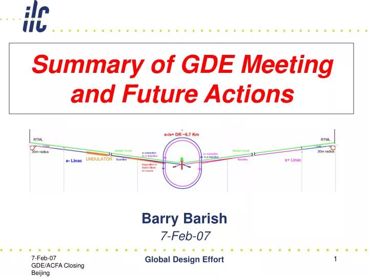
RDR ILC Schematic • 11km SC linacs operating at 31.5 MV/m for 500 GeV • Centralized injector • Circular damping rings for electrons and positrons • Undulator-based positron source • Single IR with 14 mrad crossing angle • Dual tunnel configuration for safety and availability Global Design Effort
RDR Design Global Design Effort
RDR vs ILC Physics Goals • Ecm adjustable from 200 – 500 GeV • Luminosity ∫Ldt = 500 fb-1 in 4 years • Ability to scan between 200 and 500 GeV • Energy stability and precision below 0.1% • Electron polarization of at least 80% • The machine must be upgradeable to 1 TeV The RDR Design meets these “requirements,” including the recent update and clarifications of the reconvened ILCSC Parameters group! Global Design Effort
RDR Design & “Value” Costs Summary RDR “Value” Costs Total Value Cost (FY07) 4.87B ILC Units - Shared + 1.78B ILC Units - Site Specific + 13.0K person-years (“explicit” labor = 22.2 M person-hrs @ 1,700 hrs/yr) For this estimate 1 ILC Unit = 1 US 2007$ (= 0.83 Euro = 117 Yen) • The reference design was “frozen” as of 1-Dec-06 for the purpose of producing the RDR, including costs. • It is important to recognize this is a snapshot and the design will continue to evolve, due to results of the R&D, accelerator studies and value engineering • The value costs have already been reviewed twice • 3 day “internal review” in Dec • ILCSC MAC review in Jan Global Design Effort
ILC Value – by Area Systems Main Cost Driver Conventional FacilitiesComponents Global Design Effort
Main Linac Gradient Choice • Balance between cost per unit length of linac, the available technology, and the cryogenic costs • Optimum is fairly flatand depends on detailsof technology • Current cavities haveoptimum around 25 MV/m Relative Linac Costs (from USTOS estimate) Gradient MV/m Global Design Effort
Cryomodule Value Estimates TESLA cryomodule 4th generation prototype ILC cryomodule Global Design Effort
Cost Driver - The Main Linac • Costs have been estimated regionally and can be compared. • Understanding differences require detail comparisons – industrial experience, differencdes in design or technical specifications, labor rates, assumptions regarding quantity discounts, etc. Global Design Effort
ILC Value –Global & Technical Systems Main Cost Driver Installation counted mostly as explicit labor Global Design Effort
Main Linac Double Tunnel • Three RF/cable penetrations every rf unit • Safety crossovers every 500 m • 34 kV power distribution Global Design Effort
RDR/Reviews Bid to Host Specs Preparation of Bids to Host Site Selection Process EDR (All CFS) Selection of Main Consultants Site Investigations CE + other CFS Works Machine Supply, Install, Assembly CF&S Project Schedule TENTATIVE OVERALL TIME SCHEDULE T0 = 2012 2007 2018 -5 -4 -3 -1 +1 +2 +3 +4 +5 +6 +7 -2 DRAFT Site Independent Eng. Studies (All CFS) Call for Tender Preparation (CE Works + early Services) Call for Tender Procedure (CE Works + early Services) Contract(s) Placing (CE Works + early Services) Administrative Procedures + Site Preparation Utilities Commissioning Global Design Effort R&D
RDR Report • Three Documents will be presented to the joint ICFA – ILCSC meeting tomorrow, then will be posted http://www.linearcollider.org/ • RDR Overview – (Stand alone and Chapter 1) • Draft Reference Design Report • The International Linear Collider - “Gateway to the Quantum Universe” • Thanks to all that have contributed! A fantastic accomplishment Global Design Effort
RDR Overview – Chapter 1 Global Design Effort
RDR Report – Accelerator Description + Main Linac Global Design Effort
RDR Report Nan Phinney Global Design Effort
RDR Companion Document Global Design Effort
How Good is the RDR Concept? • The design has been carried out by Area Systems that have been built up into an overall design. • We have advanced in integrating that design and even in being able to evaluate proposed changes that cross several area systems (e.g. central injector – E Paterson) • A more integrated design approach is envisioned for the engineering design stage. • Technical system designs still immature, resulting in lack of detailed specifications, requirements and value engineering has been deferred Global Design Effort
Design Challenges - Availability • ILC is has about 10x the number of operating units compared to previous accelerators with similar availabilty goal (~ 85%) • This will require significant improvements in: • Failure rates on component and sub-systems - magnets, PS, kickers, etc • Reduncancy – power, particle sources, etc • Access for maintenance and servicing – double tunnel concept • The availability issue will need much attention during engineering design phase. Global Design Effort
Design Challenges – Damping Rings Requires Fast Kicker 5 nsec rise and 30 nsec fall time 6km The damping rings have more accelerator physics than the rest of the collider Global Design Effort
Electron Cloud in Damping Rings Electron cloud buildup in an arc bend of the 6.7 km ring and suppression effect of clearing electrodes biased at the indicated voltages. 0 V 10 V 100 V Simulations show ~ 100 V is sufficient to suppress the average (and central) cloud density by two orders of magnitude. NEEDS EXPERIMENTAL DEMONSTRATION Global Design Effort
GDE R&D Board (RDB) S# Task Forces Hayano Global Design Effort
S-series Task Forces For producing R&D plans S0 : Cavity Gradient R&D S1 : Cryomodule operating gradient R&D S2 : Planning of Linac Test Facility Scale S3 : Damping Ring R&D S4 : Beam Delivery System R&D S5 : Positron Source R&D S6 : Control system R&D S7 : RF Power Source R&D Hayano Global Design Effort
S2 Task Forces Leader : T. Himel (SLAC) & H. Padamsee(Cornel) member : H. Weise, B. Kephart, C. Adolphsen N. Toge, H. Hayano (S.Nagaitsev, N.Solyak, L.Lilje, M.Ross, D. Shulte, K.Kubo) Mission :make a report of required Linac Test Facility meeting : Tele-conference every week, face-to-face in Vancouver, KEK, Valencia. document : S2charge_workplan5.doc S2_report_v5.doc http://www.linearcollider.org/wiki/doku.php?id=rdb:rdb_external:rdb_s2_home Global R&D Board (RDB) Global Design Effort Hayano
Concise S2 report Lessons learned from SRF acc. operation: CEBAF, LEP-II, Cornel, TRISTAN, KEKB, TTF(FLASH) Reasons of system tests: 28 items of possible reason are listed, and examined. such as; component reliability test, beam base feedback test, .... for minimum number of RF unit, for beam required, for being in string required, test possibility at TTF, etc. phase 1: 1 RF unit system test phase 2: continuation of test for performance improvement and industry produced modules (5 RF unit one year operation) Milestones and timeline for system tests: 2009~2011: phase 1 1 RF unit test (type 3,4 -> DFM cryomodules) ~2013: phase 2 several RF unit test (final ILC unit, multiple manufacturers) Cost estimation of system tests: total sum for phase 1 (9 cryomodules + 2 RF system) with non-beam facility and beam facility Global Design Effort Hayano
Incredibly rough Phase 1 cost estimate per system test Himel Global Design Effort
S3 Task Forces Leader : A. Wolski (Cockcroft Inst.) member : E. Elsen, J. Gao, S. Guiducci, T. Mattison, M. Palmer, M. Pivi, J. Urakawa, M. Venturini, M. Zisman Mission : Develop coordinated plan for Damping Ring R&D meeting : Tele-conference every week, face-to-face in Cornel in Sep.’06, will be in Frascati Mar. ‘07. document : https://wiki.lepp.cornell.edu/ilc/bin/view/Public/DampingRings/ https://wiki.lepp.cornell.edu/ilc/bin/view/Public/DampingRings/S3TaskForce/WebHome Prioritized list of R&D objectives, Summaries of R&D activities, Summaries of resources, Drafts of two Damping Ring R&D Plan Work Packages Global Design Effort Hayano
Damping Rings R&D Issues • The RDB S3 group has reviewed 76 R&D objectives for the damping rings, and identified 11 as "Very High Priority". These fall into the categories of: • injection/extraction kickers; • electron cloud effects; • impedance and impedance-driven instabilities; • lattice design (for good dynamic aperture, etc.); • tuning and maintaining low vertical emittance; • ion effects. • Development of a detailed R&D plan is in progress, detailing objectives, resources, milestones and timescales. • So far, draft work packages have been produced for the fast injection/extraction kickers; electron cloud studies; studies of impedance and impedance-driven instabilities. • The R&D program at present test facilities (notably, KEK-ATF) could be strengthened by future test facilities (e.g. CESR-ta and HERA-DR). • With over 25 institutions and 150 people interested or already involved, coordination of R&D efforts is a significant issue. Global Design Effort Urakawa
Electron Cloud • A draft of a detailed R&D plan has been prepared, specifying goals and milestones for a range of activities, including: • Improved modelling of electron cloud build-up. • Improved modelling of beam instabilities driven by electron cloud. • Continued laboratory investigations of a range of mitigation techniques. • Tests of mitigation techniques in operating machines. • The R&D plan takes account of resources that are, or are likely to be, available. • The present draft is still being discussed by S3: a public version should be available soon. • Many R&D activities are already in progress… Global Design Effort Urakawa
On to the EDR … • What is the EDR? • We will write down a definition, after more dialogue with the GDE and ILC communities • The general goal is to bring ourselves to the point where we are “construction ready” and can make a construction proposal. Clearly, the minimum requirement is that we have done “much of” the engineering and R&D needed before construction Global Design Effort
On the the EDR … • How do we organize work? • We propose to organize the work toward the EDR by a Project Management and through formal work packages. • A work package = a commitment for accomplishing tasks defined in our WBS • Reporting will be to GDE Project Management office • Work will be organized through MOUs + attachments having formal “statements of work” for defined time periods with defined deliverables, milestones, reporting, required resources, etc. Global Design Effort
On to the EDR … • Restructuring the GDE (see Brian Foster) • General features of present GDE organization will continues, but it will be strengthened for the EDR effort • New Features • Integrate a Project Management Office and function into the GDE • Strengthen system engineering and integration function –top level integration + continuity of technical systems • Enlarge effort, mostly in engineering areas • Develop a project WBS (in EDMS system) that defines both the breakdown of tasks or EDR work packages, and required resources for design and construction. • R&D program will be integrated with the EDR effort. Priorities, milestones, ACDs, resource allocations will be consistent with the EDR goals (also through R&D Work Packages) Global Design Effort
On to the EDR … • Timeframe for implementing new EDR structures • We have given the preliminary report (at their request) to ILCSC. (Discussion tomorrow) • The GDE dialogue we are having will continue at least until Hamburg meeting. We will appoint a task force to develop some models. • A search for a Project Manager is underway (suggestions welcome). The final plans for EDR phase will need to be “owned” by the Project Manager Global Design Effort
Summary & Final Remarks • We have produced the ILC RDR as planned! • The design is completely consistent with the ILCSC physics goals and parameters • We have produced a first version of the draft RDR that will be presented to ICFA / ILCSC tomorrow • On to the EDR !!!! Global Design Effort