Download
1 / 4
40 likes | 163 Views
Observe behavior of RSTP. PC1: 10.1.1.2. Root DGS-3324SR_A. Cable 1. Cable 2. X. DGS-3324SR_B. PC2: 10.1.1.1. Enable the STP on both units of DGS-3324SR. Check one port on DGS-3324R is blocked. PC1 and PC2 ping each continuously.

E N D
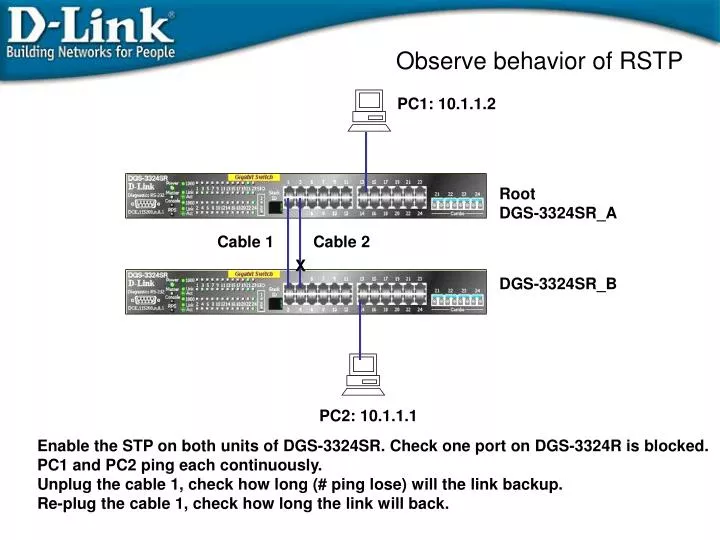
Observe behavior of RSTP PC1: 10.1.1.2 Root DGS-3324SR_A Cable 1 Cable 2 X DGS-3324SR_B PC2: 10.1.1.1 Enable the STP on both units of DGS-3324SR. Check one port on DGS-3324R is blocked. PC1 and PC2 ping each continuously. Unplug the cable 1, check how long (# ping lose) will the link backup. Re-plug the cable 1, check how long the link will back.
RSTP Example DES-3324SR_A: config ipif System ipaddress 10.1.1.10/8 enable stp config stp version rstp # Set Switch A has lower priority value so that it will be the root. # default priority=32768. config stp priority 4096 instance_id 1 config stp ports 1:5-1:24 edge true DGS-3324SR_B: config ipif System ipaddress 10.1.1.11/8 enable stp Config stp version rstp config stp ports 1:5-1:24 edge true Verify: 1. PC1 ping PC2 and PC2 ping PC1 continuously. 2. Un-plug the cable 1. Ping can recovery in around 1-2 ping loss (1-2 sec). Convergence time is about 1-2 seconds. 3. Re-plug the cable 1. Ping can recovery in around 1-2 ping loss.
PC21 192.168.1.21/24 PC31 192.168.1.31/24 v2 v3 DGS3324SR_A 1-12 13-20 23 24 T T Ports 21-24 are tagged member ports for both V2 and V3. T T v2 13-20 v3 1-12 23 24 DGS3324SR_B PC31 192.168.1.22/24 PC32 192.168.1.32/24 MSTP Example2: Traffic Load Sharing Objective: Traffic Load Sharing. V2 and V3 has it’s own RSTP. V2 active link is port 23, and V3 active link is port 24, providing load sharing. If either one of link failed, V2 and V3 uses the remained link, providing the redundancy.
MSTP Example2: Traffic Load Sharing DGS3324SR_A Configuration DGS-3324SR_B Configuration config vlan default delete 1-20 create vlan v2 tag 2 config vlan v2 add untagged 1-12 config vlan v2 add tagged 21-24 create vlan v3 tag 3 config vlan v3 add untagged 13-20 config vlan v3 add tagged 21-24 enable stp config stp version mstp config stp mst_config_id name abc config stp mst_config_id revision_level 1 create stp instance_id 2 config stp instance_id 2 add_vlan 2 create stp instance_id 3 config stp instance_id 3 add_vlan 3 ## adjust stp priority so that switchA is the root. config stp priority 4096 instance_id 0 config stp priority 4096 instance_id 2 config stp priority 4096 instance_id 3 ## adjust port priority so that port 23 is the active port ## for v2, port24 is the active port for v3. config stp mst_ports 1:23 instance_id 2 priority 96 config stp mst_ports 1:24 instance_id 3 priority 96 config stp ports 1-20 edge true config vlan default delete 1-20 create vlan v2 tag 2 config vlan v2 add tagged 21-24 config vlan v2 add untagged 1-12 create vlan v3 tag 3 config vlan v3 add tagged 21-24 config vlan v3 add untagged 13-20 enable stp config stp version mstp config stp mst_config_id name abc config stp mst_config_id revision_level 1 create stp instance_id 2 config stp instance_id 2 add_vlan 2 create stp instance_id 3 config stp instance_id 3 add_vlan 3 config stp ports 1-20 edge true ## Debug command for A and B show stp instance_id show stp ports