Download
1 / 31
370 likes | 828 Views
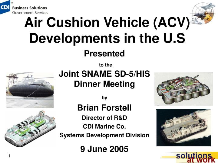
Air Cushion Vehicle (ACV) Developments in the U.S. Presented to the Joint SNAME SD-5/HIS Dinner Meeting by Brian Forstell Director of R&D CDI Marine Co. Systems Development Division 9 June 2005. Anatomy of an ACV.

E N D
Air Cushion Vehicle (ACV) Developments in the U.S Presented to the Joint SNAME SD-5/HIS Dinner Meeting by Brian Forstell Director of R&D CDI Marine Co. Systems Development Division 9 June 2005
Anatomy of an ACV • ACVs are truly Amphibious Craft that are capable of traveling over almost any type of surface. • Capability comes from ACV unique equipment.
Anatomy of an ACV ACV unique equipment includes: • Skirt System • Lift System • Air Screw Propulsors • Bow Thrusters
Skirt Systems • Continued to evolve and mature over the next 20+ years. • Evolved into the typical Bag-Finger Skirt. • Peripheral bag for air distribution. • Flexible fingers attached to bag. • Cushion sub-division. • Flexible Skirt Systems were first introduced to ACVs in 1961.
Deep Skirt Project • Oct. 1995, CNO N853 directs development of Enhancements for Increasing LCAC Survivability while conducting Shallow Water MCM Mission (SWMCM). • Jan. 1996, Coastal Systems Station is directed by PEO-CLA, PMS-377 to initiate Deep Skirt Project.
Deep Skirt Design • Principal Characteristics • 40% Increase in Cushion Height • Elimination of Longitudinal Cushion Divider • Double-Bubble Side Seal for Well-Deck Compatibility • Unique Back-to-Back Side Fingers for enhanced roll static stability Represented the “First” of a New Generation of Skirt Designs
Deep Skirt Design Deep Skirt design was subjected to extensive sub-scale test prior to committing to full-scale prototyping
Deep Skirt Design • SWMCM Mission was cancelled after the prototype was built! • Performance and durability testing of Deep Skirt showed: • Improved Ride Quality • Improved Payload Carrying Capability • Improved Speed/Sea State Performance Deep Skirt was Retained as a Craft Upgrade and is in Production
Not All Is Good • Material Delamination showed up after 100 operating hours on the prototype skirt. • Issue also showed up on the Canadian Coast Guard AP.1-88/200 and the Hoverspeed SR.N4 MKIII. • All three craft used the same natural rubber material. Suspected that Fatigue was the Primary Failure Mode
Not All Is Good • FEA analysis of an inflated finger indicated Stress Concentrations and areas of Large Deformations. Stress Map Deflection Map
Things Get Better • FEA analysis indicated that a modification of the Design & Lofting Process would correct this. Deflection Map before Modification Deflection Map after Modification
Second & Third Generation Designs • Lessons Learned were applied to the Finnish T-2000 Combat ACV (2nd Gen). • Modified Design/Lofting Process • 3-D Design Tools
Second & Third Generation Designs • 2nd Generation T-2000 Skirt has 440+ hours on original bow and side fingers. • Stern corner and stern fingers replaced after approximately 300 hours.
Second & Third Generation Designs • 3rd Generation Skirt is being manufactured. • Model test data results indicate that this will be the best design so far. Believe that Additional Performance Improvements are Possible
Lift Fan Design • Historically, ACVs tended to use commercially available fans or a version of the successful HEBA-A or HEBA-B Fan Series. • Current and future high-density craft are requiring higher pressure, higher air-flow rate and increased efficiency. • Typically military craft rather than commercial craft.
Lift Fan Design • Systematic series fan tests have not been performed since the mid to late 60’s. • Many of these are documented in “Unpublished” Reports. • Results have been the primary design guide for: • Fan Aerodynamic Design • Volute Design • Installation Effects
Lift Fan Design • CDIM-SDD participated in a Science and Technology (S&T) effort directed at fan design. • ONR Sponsorship. • Directed at using Modern CFD Tools to develop lift fans that Improve on Performance and Efficiency achievable with current equipment. • Aerodynamic design drew on prior fan design experience at CDIM-SDD.
Typical CFD Results Volute Static Pressure Distribution Impeller Pressures and Velocity Vectors
Lift Fan Design • CFD tools allowed efficient and economical examination of the various fan design parameters. • Results indicated that: • Blade stall is Very Difficult To Avoid in heavily loaded fan designs. • Good fan performance can be achieved even with some stall present. • Volutes can be Much Smaller than previously thought without sacrificing fan performance.
Fan Model Test Sub-Scale Model Tests Conducted in October 2003 Test Results Generally Confirmed CFD Analysis Results
Ducted Propulsors • Ducted air-screw design has typically relied on Potential Flow Theory, Strip Analysis or, in some cases, Lifting Line Theory. • Designs are developed for free-stream conditions. • Ignores Installation Effects. • Full-scale trials experience indicates that these designs typically produce Significantly Less Thrust than expected.
Ducted Propulsors • CDIM-SDD participated in a Science and Technology (S&T) effort directed at ducted propulsor design. • ONR Sponsorship. • Directed at using Modern CFD Tools to develop designs that Improve on Performance and Efficiency achievable with current equipment. • Aerodynamic design considered the actual installed condition.
LCAC CFX Computational Model Tool Verification • LCAC propulsor was analyzed prior to starting the new design. • Checked against known performance. • Results compared favorably. CFX for LCAC at 25 knots (Midway Station 7’6”)
TYPICAL CFD RESULTS Flow Field in Front of the Prop and Shroud Flow Field in Front of the Prop and Shroud
Propulsor Model in Glenn L. Martin Wind Tunnel • 1/6th Scale Propulsor Tests • CFD Simulated Wind Tunnel Tests were performed prior to actual physical testing.
Model Test Results • Model Generally Performed as Good or Better than CFD Predictions • Measured Ct agreed with CFD Predictions 5% • Measured Cq 10% less than CFD Predictions Results Generally Validated the Design Tool and Approach
Bow Thruster Nozzles • Bow Thrusters are used on many modern ACV designs. • Enhance Maneuverability • Augment Thrust from Main Propulsors • Provide Some Redundancy to Main Propulsors
Bow Thruster Nozzles • Typical Bow Thruster Nozzle • Easy to Manufacture • Aerodynamically Inefficient • Easy Bend versus Hard Bend • Large Over-Turning Moment on Bearing
Bow Thruster Nozzles Low-Profile Bow Thruster • Aerodynamically Efficient Cascade • Significant Reduction in “Over-Turning” Moment on Bearing • Reduced Visual & Radar Signature • Complex to Manufacture Full-Scale Trials Verified Aerodynamic Efficiency