Download
1 / 17
190 likes | 550 Views
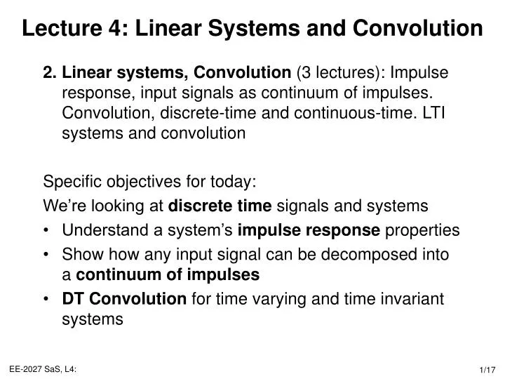
Lecture 4: Linear Systems and Convolution. 2. Linear systems, Convolution (3 lectures): Impulse response, input signals as continuum of impulses. Convolution, discrete-time and continuous-time. LTI systems and convolution Specific objectives for today:

E N D
Lecture 4: Linear Systems and Convolution • 2. Linear systems, Convolution (3 lectures): Impulse response, input signals as continuum of impulses. Convolution, discrete-time and continuous-time. LTI systems and convolution • Specific objectives for today: • We’re looking at discrete time signals and systems • Understand a system’s impulse response properties • Show how any input signal can be decomposed into a continuum of impulses • DT Convolution for time varying and time invariant systems
Lecture 4: Resources • SaS, O&W, C2.1 • MIT Lecture 3
Introduction to Convolution • Definition Convolution is an operator that takes an input signal and returns an output signal, based on knowledge about the system’s unit impulse response h[n]. • The basic idea behind convolution is to use the system’s response to a simple input signal to calculate the response to more complex signals • This is possible for LTI systems because they possess the superposition property (lecture 3): System y[n] = h[n] x[n] = d[n] System: h[n] y[n] x[n]
actual value Impulse, time shifted signal Discrete Impulses & Time Shifts • Basic idea: use a (infinite) set of of discrete time impulses to represent any signal. • Consider any discrete input signal x[n]. This can be written as the linear sum of a set of unit impulse signals: • Therefore, the signal can be expressed as: • In general, any discrete signal can be represented as: The sifting property
Example • The discrete signal x[n] • Is decomposed into the following additive components • x[-4]d[n+4] + x[-3]d[n+3] + x[-2]d[n+2] + x[-1]d[n+1] + …
Discrete, Unit Impulse System Response • A very important way to analyse a system is to study the output signal when a unit impulse signal is used as an input • Loosely speaking, this corresponds to giving the system a kick at n=0, and then seeing what happens • This is so common, a specific notation, h[n], is used to denote the output signal, rather than the more general y[n]. • The output signal can be used to infer properties about the system’s structure and its parameters q. System: q h[n] d[n]
Types of Unit Impulse Response Causal, stable, finite impulse response y[n] = x[n] + 0.5x[n-1] + 0.25x[n-2] • Looking at unit impulse responses, allows you to determine certain system properties Causal, stable, infinite impulse response y[n] = x[n] + 0.7y[n-1] Causal, unstable, infinite impulse response y[n] = x[n] + 1.3y[n-1]
Linear, Time Varying Systems • If the system is time varying, let hk[n] denote the response to the impulse signal d[n-k] (because it is time varying, the impulse responses at different times will change). • Then from the superposition property (Lecture 3) of linear systems, the system’s response to a more general input signal x[n] can be written as: • Input signal • System output signal is given by the convolution sum • i.e. it is the scaled sum of impulse responses
Example: Time Varying Convolution • x[n] = [0 0 –1 1.5 0 0 0] • h-1[n] = [0 0 –1.5 –0.7 .4 0 0] • h0[n] = [0 0 0 0.5 0.8 1.7 0] y[n] = [0 0 1.4 1.4 0.7 2.6 0]
Linear Time Invariant Systems • When system is linear, time invariant, the unit impulse responses are all time-shifted versions of each other: • It is usual to drop the 0 subscript and simply define the unit impulse response h[n] as: • In this case, the convolution sum for LTI systems is: • It is called the convolution sum (or superposition sum) because it involves the convolution of two signals x[n] and h[n], and is sometimes written as:
x[n] y[n] System: h[n] System Identification and Prediction • Note that the system’s response to an arbitrary input signal is completely determined by its response to the unit impulse. • Therefore, if we need to identify a particular LTI system, we can apply a unit impulse signal and measure the system’s response. • That data can then be used to predict the system’s response to any input signal • Note that describing an LTI system using h[n], is equivalent to a description using a difference equation. There is a direct mapping between h[n] and the parameters/order of a difference equation such as: • y[n] = x[n] + 0.5x[n-1] + 0.25x[n-2]
Example 1: LTI Convolution • Consider a LTI system with the following unit impulse response: • h[n] = [0 0 1 1 1 0 0] • For the input sequence: • x[n] = [0 0 0.5 2 0 0 0] • The result is: • y[n] = … + x[0]h[n] + x[1]h[n-1] + … • = 0 + • 0.5*[0 0 1 1 1 0 0] + • 2.0*[0 0 0 1 1 1 0] + • 0 • = [0 0 0.5 2.5 2.5 2 0]
Example 2: LTI Convolution • Consider the problem described for example 1 • Sketch x[k] and h[n-k] for any particular value of n, then multiply the two signals and sum over all values of k. • For n<0, we see that x[k]h[n-k] = 0 for all k, since the non-zero values of the two signals do not overlap. • y[0] = Skx[k]h[0-k] = 0.5 • y[1] = Skx[k]h[1-k] = 0.5+2 • y[2] = Skx[k]h[2-k] = 0.5+2 • y[3] = Skx[k]h[3-k] = 2 • As found in Example 1
Example 3: LTI Convolution • Consider a LTI system that has a step response h[n] = u[n] to the unit impulse input signal • What is the response when an input signal of the form • x[n] = anu[n] • where 0<a<1, is applied? • For n0: • Therefore,
Discrete LTI Convolution in Matlab • In Matlab to find out about a command, you can search the help files or type: • >> lookfor convolution • at the Matlab command line. This returns all Matlab functions that contain the term “convolution” in the basic description • These include: • conv() • To see how this works and other functions that may be appropriate, type: • >> help conv • at the Matlab command line • Example: • >> h = [0 0 1 1 1 0 0]; • >> x = [0 0 0.5 2 0 0 0]; • >> y = conv(x, h) • >> y = [0 0 0 0 0.5 2.5 2.5 2 0 0 0 0 0]
Lecture 4: Summary • Any discrete LTI system can be completely determined by measuring its unit impulse response h[n] • This can be used to predict the response to an arbitrary input signal using the convolution operator: • The output signal y[n] can be calculated by: • Sum of scaled signals – example 1 • Non-zero elements of h – example 2 • The two ways of calculating the convolution are equivalent • Calculated in Matlab using the conv() function (but note that there are some zero padding at start and end)
Lecture 4: Exercises • Q2.1-2.7, 2.21 • Calculate the answer to Example 3 in Matlab, Slide 14