Download
1 / 15
150 likes | 276 Views
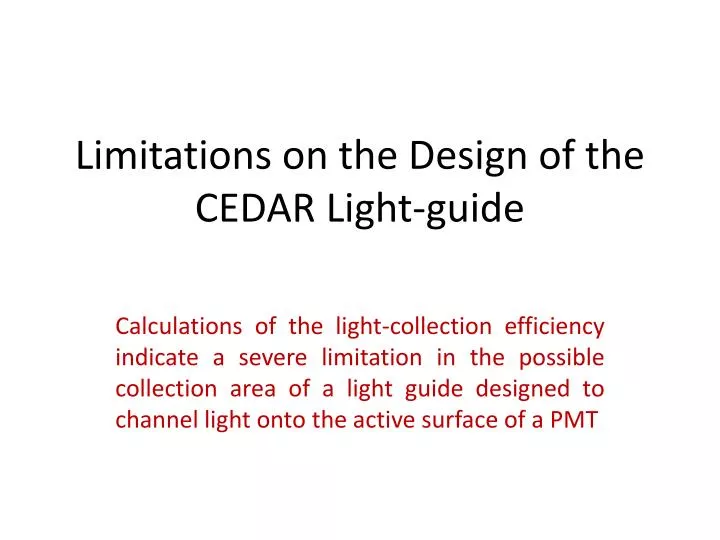
Limitations on the Design of the CEDAR Light-guide. Calculations of the light-collection efficiency indicate a severe limitation in the possible collection area of a light guide designed to channel light onto the active surface of a PMT.

E N D
Limitations on the Design of the CEDAR Light-guide Calculations of the light-collection efficiency indicate a severe limitation in the possible collection area of a light guide designed to channel light onto the active surface of a PMT
Light from each of the 8 quartz windows is reflected off a 45o mirror and illuminates the area covered by (approximately) 30 PMTs A lightguide must channel the light onto the active regions of the PMTs with high efficiency Limitations on the Design of Light-guides: NA62 Collaboration Meeting Brussels September 2010
Bristol Simulation Light from quartz windows (blue) reflects off 45o ellipsoidal mirrors to Illuminate PMTs (green). Active surface of PMTs covers about 20% of the illuminated area so lightguide (red) consisting of a set of conical reflectors (L = 25 mm) channels the light onto the PMTs. Taking account of Fresnel reflection at PMT glass surface and multiple reflection on conical surfaces about 90% of light reaches PMTs. Can we do better? Limitations on the Design of Light-guides: NA62 Collaboration Meeting Brussels September 2010
First a problem to confront ... • MC work by Angela Romano (Birmingham) • indicates non-uniform light intensity across • the PMT plane. If uncorrected we would need • to increase the number of PMTs to avoid the • central ones saturating - and the outer PMTs • would then be used inefficiently. • Liverpool addressed this problem by designing • a lightguide with cones of variable light-collection area to equalise the signal in each PMT. We can make it in our workshop ... • ... But, will it work? • How does the light-collection efficiency • vary with the incident area of the cone? • What is the effect of varying the cone length • or changing from a flat geometry? Limitations on the Design of Light-guides: NA62 Collaboration Meeting Brussels September 2010
A serious issue – Part I Only a small fraction of the incident light reaches the active surface of the PMT without reflection off the conical surface of the lightguide. After m reflections the angle of incidence on the PMT glass envelope is α + 2m β For large α, β, or m this angle exceeds 90o meaning that light is reflected backwards from the conical surface and does not reach the PMT. eg AB = 8, AN = 30, CD = 24 mm No incident light reaches the PMT, even for the most central PMT with small angle α, if there are more than 2 reflections. The problem is much worse for outer PMTs where α is 0.1 – 0.2 radians S B A R (α+3β) β (α+β) Q C D N α Limitations on the Design of Light-guides: NA62 Collaboration Meeting Brussels September 2010
A serious issue – Part II Photons reaching the PMT at an incident angle > 60o have a rapidly increasing probability of being reflected – and hence lost. This occurs for just 2 reflections off the conical surface for large diameter. Low photon statistics compound the problem because of poor quantum efficiency (20%) in converting photons to electrons. The loss of one photon may make the difference between success and failure in detection of a group of photons by a PMT. n = 1.5 Averaged polarisation Limitations on the Design of Light-guides: NA62 Collaboration Meeting Brussels September 2010
Methodology I – Central PMT • Illuminate a conical reflector with light from a point source on the axis of the cone – cylindrical symmetry: • Calculate the contributions to the effective collection area from direct light and that reflected from the conical surface, taking into account Fresnel reflection at the PMT surface; • Calculate the efficiency as the ratio of effective to total area; • Vary the ‘collection’ cone diameter while keeping constant the ‘exit’ diameter to match the active area of the PMT. • Repeat the above for different cone lengths. Limitations on the Design of Light-guides: NA62 Collaboration Meeting Brussels September 2010
S B A Geometry: AB = 2a = 8 mm CD = 2b > 18 mm AN = L = 30 mm [typically] R0 = 300 mm from PMT to mirror • β is the angle of the cone tanβ = (b – a) / L • α is angle of light incident from mirror Coordinates: D (0, 0) A ((b-a), L) B ((b+a), L) C (2b, 0) Q (y1tanβ, y1) • P (b, -(R0 - L)) [extrapolated view] R (α+3β) β (α+β) Q C D N α P Limitations on the Design of Light-guides: NA62 Collaboration Meeting Brussels September 2010
A photon will hit the PMT without reflection if: A photon impacting the cone at Q(x1, y1), where: will suffer just one reflection if: A photon reflecting a second time at R(x2, y2) will have coordinates: This photon strikes the PMT at Sanity Checks: If y2 > L, then only 1 reflection has occurred; If y2 < L and X < (b-a), then > 2 reflections have occurred; If X > (a + b) then the photon is reflected backwards. Limitations on the Design of Light-guides: NA62 Collaboration Meeting Brussels September 2010
Results for a central cone of L= 30 mm show: i) A slow decrease in efficiency for cone diameter >18 mm due to increased Fresnel reflection at the PMT; ii) A rapid decrease in efficiency for cone diameter >25 mm because an increasing fraction of light from the second reflection fails to reach the PMT; iii) The effective collection area actually decreases for CD > 25 mm. Limitations on the Design of Light-guides: NA62 Collaboration Meeting Brussels September 2010
Results for central cone of reduced length L= 20 mm show: i) Greatly reduced acceptance with cone diameter mainly because of the increasing probability of photons reflecting backwards after 2 reflections; ii) The ‘safe’ cone diameter is now reduced to 21 mm, even for small α Limitations on the Design of Light-guides: NA62 Collaboration Meeting Brussels September 2010
Methodology II – Outer PMT • Typical irradiance angles for outer PMTs are α = 0.2 radians. • We no longer have cylindrical symmetry about the axis of the cone and an analytical treatment is too complex without approximation. • One approach would be to maintain cylindrical symmetry and set R0 to be 100 mm instead of 300 mm. However, the central part of the cone would then always be illuminated at small angles and the outer regions at large angles – a horrible systematic bias. • I have chosen a different bias by using an offset angle. All parts of the cone are irradiated at angles varying around this offset angle in a symmetrical way. This is only approximately true, but does have the advantage of averaging over the whole cone. • I show indicative results for offsets of 0.1 and 0.2 radians. This study must be repeated properly using MC ray-tracing. Limitations on the Design of Light-guides: NA62 Collaboration Meeting Brussels September 2010
Indicative Efficiency for Outer PMTs Limitations on the Design of Light-guides: NA62 Collaboration Meeting Brussels September 2010
Conclusions • We must ensure that all photons that reflect twice on the conical surface reach the PMT with a low probability of Fresnel reflection – hence reject 20 mm cone length; • We have some leeway in relaxing the spacing of central PMTs but little or none in increasing the spacing of outer ones – which we would like to do in order to increase the ratio of collection area to that of inner PMTs; • To solve the above difficulties we need one or more of: • Clever mirror geometry that produces a more uniform intensity distribution to favour equal spacing of PMTs; • A reduction in the angular spread of light from the mirror; • Light-guide (and PMTs) forming a spherical rather than planar surface so that light from the mirror is parallel to the cone axis. Limitations on the Design of Light-guides: NA62 Collaboration Meeting Brussels September 2010
Summary of Results Limitations on the Design of Light-guides: NA62 Collaboration Meeting Brussels September 2010