Download
1 / 13
130 likes | 261 Views
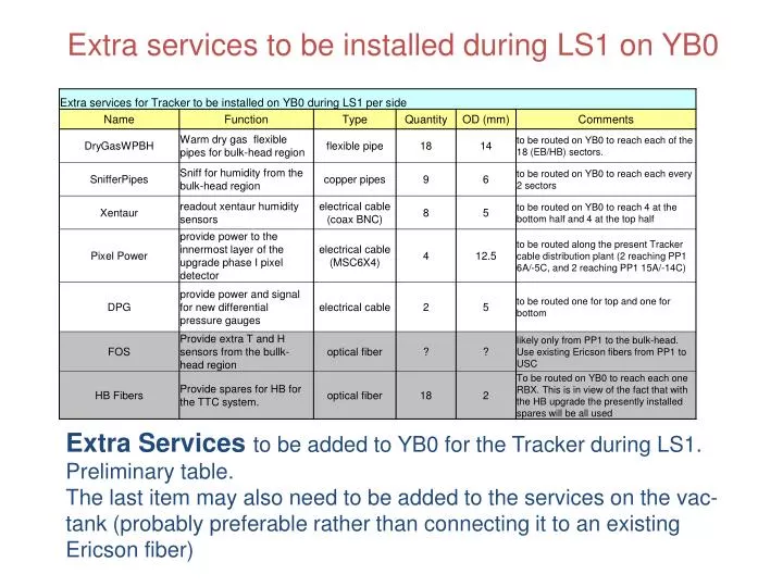
Extra services to be installed during LS1 on YB0. Extra Services to be added to YB0 for the Tracker during LS1 . Preliminary table. The last item may also need to be added to the services on the vac -tank (probably preferable rather than connecting it to an existing Ericson fiber). + Z.

E N D
Extra services to be installed during LS1 on YB0 • Extra Services to be added to YB0 for the Tracker during LS1. • Preliminary table. • The last item may also need to be added to the services on the vac-tank (probably preferable rather than connecting it to an existing Ericson fiber)
+Z 5 1 12 8 9 • Main issue: find space on the radial surface of YB0 to access the vac-tank. Once on the vac-tank there is much more space to move around (although still complex). • Proposal: use already existing EB/HB Rest cable trays which still have a reasonable amount of free space.
Extra Services total cross-section is ~45 cm2per side (at this moment). • Example: • Considering the extra dry air pipes on the +Z side. • Need to distribute 18 extra dry air pipes. We could consider adding 4 pipes on EB/HB Rest radial cable tray on muon sectors 5 and 9 and 5 pipes on muon sectors 1 and 8.
Example: Muon Sector 9 14 15 (b) 16 (a) • Need to feed 4 PP1s, for example: 14,15,16,17. • Follow EB/HB Rest cables, cross over EB-LV cables (a) and mount on the OF cable trays (b) and from there feed the chosen PP1s. • Alternatevely, once on the vac-tank, they could follow EB-LV cables
Additional cooling pipes for Pixel Phase I upgrade: preliminary look Possible pipe configuration • Most important: • Find space on the radial section • Minimize the routing complexity on the vac-tank 80mm 70mm 19mm cryogel Example again on Muon Sector +9 SECTOR +9 Space available on the side of the ECAL rest cable tray is about 85mm in height by 70mm in width. Red protruding objects are DT gas feeder connectors.
+14C 9 From Muon sector +9 we need to reach PP1 +14C, shown in the picture.
+14C About 90mm diameter space available next to the thermal screen supports on the vac-tank. There is a straight shot from the muon iron to the edge of the vac-tank
Muon sector 1 95 96 Muon sector 9 86 96
Settore 5 PP1 +5C Pixel inlet Cold Dry Gas Pipes inlet Thermal Screen inlet Thermal Screen outlet
Settore 5 In nero sono indicati gli spaziatori di plastica da 3 mm di spessore See next slide
S T U V W 1 2 3 4 Pixel inlet Cold Dry Gas Pipes inlet Thermal Screen inlet Thermal Screen outlet