Download

1 / 29
290 likes | 294 Views
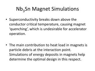
Current-Field Instabilities in High Performance Nb 3 Sn Strands in Moderate Fields. M.D. Sumption, E.W. Collings Funded by DOE HEP Grant DE-FG02-95ER40900. Importance of Strand Stability and relationship to the Magnet Load Line. Spread of load lines for “Magnet B”.

E N D
Current-Field Instabilities in High Performance Nb3Sn Strands in Moderate Fields M.D. Sumption, E.W. Collings Funded by DOE HEP Grant DE-FG02-95ER40900
Importance of Strand Stability and relationship to the Magnet Load Line Spread of load lines for “Magnet B” Take Home Message from Fermi Stability Workshop 2004 Regime of instability Spread of load lines for “Magnet A” 12 T
Outline • Introduction: Instability Types SC (“flux jump”) rather than cryostability Three Regimes - Manifestations of Same • Experiment – Obs. of Middle Field Instability • Model All Descriptions start with Heat Balance Model including both RRR and Enthalpy • Comparisons and Physical Consequences Prediction of Is -- Js RRR helpful in high fields in presence of cooling deff controlling at low fields or absence of cooling
Two varieties—seen at OSU, NIST, Fermi (a) Strands with Complete FJ (b) Strands with Partial Flux Jumps Low Field Flux Jumping in M-H loops Larger, partial FJ at higher B Fine “hair” FJ Near complete FJ at higher fields Fine “hair” FJ at lower fields
High Field I-V with very small over-voltage limits –Marginal stability Seen by all measuring Jc in High Performance Sn – Fermi, LBNL, BNL, OSU, NIST, others Obs: Achievable Over-Voltage Drops with Increasing Current Obs: Strand quenches during early part of I-V SC transition OST 113-B1 MJR
Intermediate Regime Flux Jumping Below 2.5 T But, Instabilities above 2.5 T -- up to 8 T, then OK Observation: Dangerous Instabilities in I-V at field where no M-H FJ exist Observed initially at Fermilab (Barzi) E. Barzi from NIMS 2004
Fermilab observation of current enabled FJ Recent Studies LBNL observation of Is limits Barzi LBNL • Fermilab Stability Calculations • Fermilab pointed out importance of Enthalpy considerations, (following, e.g. Hancox): Vadim Kashikhin, Zlobin, e.g., IEEE --5LB02 ASC
BNL, A. Ghosh, Cooley RRR dependence must be included S. Feher, MT-18 G. Ambrosio, ASC 2004
STRAND A RESULTS Black, Red – Standard JcJclim = 1200 A Green = H, J B Jclim Blue = H, J B 1000A
Strand A: Field Ramping Low field “hash” in both cases, full FJ in ramp-up case V and dM/dt spikes corellated
Setting up the Generic Problem All stability calculations concerning the SC material (as opposed to cryostability, which focuses on the stabilizer), start from the following heat balance
Results for Slab (Wilson) 2 4 3 1 Heat Generated by Flux incursion Heat removed by cryogen Heat Perturbation 2a Heat absorbed by strand (delta T) Jc is the change in Jc due to the heat pulse a is the slab width C = volumetric specific heat h = heat transfer coefficient J = time constant for shielding current decay
2a Results for Slab Conductor, with Cu stabilization layers and current Centerline shift (increases flux motion and energy Herei = I/Ic, and v is a cooling parameter Time constant increase due to longer current decay
For Round Strands For round strands, Term 1 and Term 3 OK Term 2: needs modified for cylinder magnetization Term 4: Heat removal from cylinder rather than slab Ignoring for a moment the magnetization change (expect order of 20-30%) but changing the heat removal term, we get (very similar to Wilson)
Basic Implications deff based magnetization/ Heat Capacity Influence of cooling LHS < RHS for stability Influence of Current How Important is RRR? If h = 103, then But it is 10 x greater in nucleate boiling regime
Calculation: II: What is Jlimit? So, starting with What j = J/Jc can be reached before full instability occurs? Setting = 1, we find Settingi = I/Ic = J/Jc = j we find
Calculation: III Replacing CTc with the full heat capacity term Hv Using Tc = Tc0(1-b)1/1.52[Godeke, Maki-De-Gennes], we find only the cubic term matters and Hv (/4)Tc04(1-b)2.63 We integrate up to the current sharing temperature, Tcs. Since Jc=Jc0(1-T/Tc), we can set T = Tcs, and find that Tcs = Tc(1-j). Thus, also using
Summary Calculation Results Which h to use? At right we use hnb = 104 W/m2K if T < 1 K hfb= 103 W/m2K if T < 1 K Also have “potted magnet” curves where h = hfbthroughout hnb hfb
Influence of RRR – Time, not thermal Conductivity Thermal Transport Inside Strand – radial, K-limited Pc Ps Heat Transfer into Liq He For pool Boiling conditions
RRR time vs K in potted systems In the case where we are not in direct contact with He, we are either transferring to neighboring regions, or out to the bath. In either case, the relevant parameter is <K> Taking 125 m as the insulation thickness, 1 mm as the strand OD, and 0.3 W/mK as the thermal conductivity of the insulation Which is just the winding-pack-fraction normalized insulation K
Re-configuring Expressions for case of potted magnets-I Equation for JI has a factor which assumes cooling via pool boiling, and thus h In Cryogen In potted system
Re-configuring Expressions for case of potted magnets-I h K/l If l = 20 mm, then RRR/140 -- factor of 3 worse than assumptions behind h = 103 W/m2K
Note that for full adiabatic stability this requires Which is about 25 microns But for situations with good cooling Js (1/deff)*RRR1/2
CONCLUSIONS (1) RRR-induced dynamic stability is important – it lets us squeeze out an important margin (2) deff minimization important, especially at very low fields – BUT deff is a stand-in for magnetization (3) RRR up to 100 is beneficial (only limited by magneto-resistance) (4) RRR needs to be high within the strand – not just on the outside – main influence is by time constant, not heat conduction (5) For potted systems, RRR will still help, but less