Download
1 / 14
140 likes | 157 Views
AERODYNAMIC OPTIMIZATION OF REAR AND FRONT FLAPS ON A CAR. University of Genova – Polytechnic School Advanced fluid dynamics course 2015/2016. Student : Giannoni Alberto Professor: Ing. Jan Pralits Co-Professor: Ing. Matteo Colli. PRESENTATION OF THE WORK.

E N D
AERODYNAMIC OPTIMIZATION OF REAR AND FRONT FLAPS ON A CAR University of Genova – Polytechnic School Advanced fluiddynamicscourse 2015/2016 Student: Giannoni Alberto Professor: Ing. Jan Pralits Co-Professor: Ing. Matteo Colli
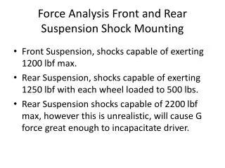
PRESENTATION OF THE WORK • Active and smartaerodynamicisbecomingessential for sportscars. • Moving flaps at the rear and the front seemed to be the mostefficient way to ensurestability and downforcewithoutincreasing drag toomuch. • In thisprojectwewouldlike to investigate performances of four flaps installed on a real-size car through the OpenSource CFD Software . Aerodynamic optimization of rear and front flaps on a car
Development of the analysis • Sequence of phases: 1. Geometrycreation in a CAD program and modification of flap’sangles 2. Mesh generation and refinement for the wholecases 3. CFD simulationusingOpenFoam software 4. Convergencestudy and post-processing 5. CL and CDevaluation 6. Looking for the optimalvalue of angles Aerodynamic optimization of rear and front flaps on a car
1) GeometriesCreation Geometrywasimplemented in ProE software respecting the actualdimensions of a sport car on market sale: Thensixcombination of incidenceangleswerecreated for the future optimization work: STL File Aerodynamic optimization of rear and front flaps on a car
2) Mesh generation and refinement Meshingis the mostimportant part in CFD, necessary to solve N-S equations OpenFoamcomes with a powerfultool for that: • blockMesh for a background mesh • snappyHexMesh for the iterative refinement: • specific and betterrefinement in certain zone suchaswakeregion. First step: cellsthatdon’tlieinto the regionoutside the car with atleast 50% of volume are removed. Second step: moving cell vertex points onto surface geometry to remove the jagged castellated surface from the mesh. Third step: addition of a specified number of layers following the geometry Aerodynamic optimization of rear and front flaps on a car
2) Mesh generation and refinement 4 layersnearby the ground 2 layersnearby the car Additionalrefinement with RefineWallLayer 3,9 million of cells Aerodynamic optimization of rear and front flaps on a car
3) CFD Simulation in OpenFoam • OpenFoamsolves N-S equationusingturbulencemodels RANS equations • Extra termsmodellingk-ω SST model • Solver SimpleFoam: incompressible, steady-state, turbulentflows. Boundary Conditions Pressurenormalgradientequal to zero for the Inlet and the Ground. Front, back and top are slip condition, Outlet has a fixed zero value. Velocitynormal component equal to zero for front, back and the top of the domain. Fixedvalue for the Inlet and the Ground. Outlet isInletOutlet. back outlet ground inlet front Aerodynamic optimization of rear and front flaps on a car
4) Post-Processing: Yplus After the simulationhasrun the checking of some parametersisrequired to validate the solution, otherwise the grid or some values in solvingmethods (fvScheme/solution) should be changed. Aboundary layer optimization was carried out based on the y+ parameter. This is defined as wall distance units , using the following equation: Where y is the distance to the first cell centre normal to the wall, and Uτ is the friction velocity and is equal to: It is normally considered an acceptable value if less than 300. Aerodynamic optimization of rear and front flaps on a car
4) Post-Processing: CL and CD • CL and CDwereprocessed for eachgeometryimplementing the appropriate dictionary in system folder. Obvoiuslyisnecessarythatthosevaluestend to converge after the first iterations. • Using gnuplotitispossible to verifyit: Aerodynamic optimization of rear and front flaps on a car
5) Results: first geometry High velocityregionunderneath the car due to the sectionrestriction. Wake developmentatseveraliterations Aerodynamic optimization of rear and front flaps on a car
5) Results: othergeometries 40°-40° degrees 40°-30° degrees Aerodynamic optimization of rear and front flaps on a car
5) Results: othergeometries 50°-40° degrees 50°-15° degrees 50°-30° degrees Aerodynamic optimization of rear and front flaps on a car
6) Performance optimization Purpose of the project: Evaluateaerodynamiccoefficients for a car with four flaps varyingtheiranglesamong discrete values. CL with zero inclination for all of the flaps isalready negative. Decide a combination of anglesthatmaximize CL withoutintroducingtoomanylosses. Aerodynamic optimization of rear and front flaps on a car
7) Future developments • This was a simplified analysis of the problem as an initial case study: a more complicated one could be carried out certainly with: • a more detailed geometry and a more refined mesh, • velocity of the car should be increased till 200 or 300 km/h, • non-aligned inlet flow should be investigate to simulate cornering that is the main situation in which stability must be provided by the flaps. THANKS FOR YOUR ATTENTION Aerodynamic optimization of rear and front flaps on a car