Download
1 / 37
460 likes | 810 Views
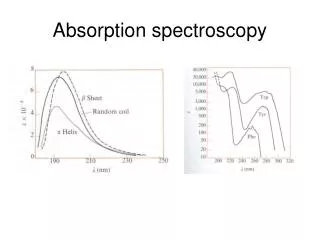
Absorption Spectroscopy. Introduction A.) Absorption : electromagnetic (light) energy is transferred to atoms, ions, or molecules in the sample. Results in a transition to a higher energy state. Transition can be change in electronic levels, vibrations, rotations, translation, etc.

E N D
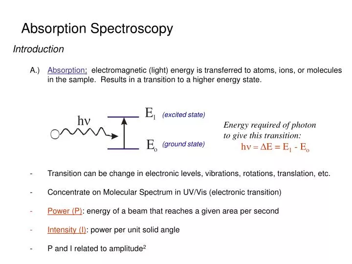
Absorption Spectroscopy Introduction A.) Absorption: electromagnetic (light) energy is transferred to atoms, ions, or molecules in the sample. Results in a transition to a higher energy state. • Transition can be change in electronic levels, vibrations, rotations, translation, etc. • Concentrate on Molecular Spectrum in UV/Vis (electronic transition) • Power (P): energy of a beam that reaches a given area per second • Intensity (I): power per unit solid angle • P and I related to amplitude2 (excited state) Energy required of photon to give this transition: hn =DE= E1 - Eo (ground state)
B.) Terms: 1.) Beer’s Law: A = ebc The amount of light absorbed (A) by a sample is dependent on the path length (b), concentration of the sample (c) and a proportionality constant (e – molar absorptivity) Amount of light absorbed is dependent on frequency (n) or wavelength (l) c Increasing Fe+2concentration Absorbance is directly proportional to concentration Fe+2
B.) Terms: 1.) Beer’s Law: A = ebc Transmittance (T) = P/Po %Transmittance = %T = 100T Absorbance (A) = log10 Po/P No light absorbed- % transmittance is 100% absorbance is 0 All light absorbed- % transmittance is 0% absorbance is infinite
Relationship Described in Terms of Beer’s Law A = Absorbance = ebc = -log(%T/100) e = molar absorptivity: constant for a compound at a given frequency (n) or wavelength (l) units of L mol-1 cm-1 b = path length: cell distance in cm c = concentration: sample concentration in moles per liter. Therefore, by measuring absorbance or percent transmittance at a given frequency can get information related to the amount of sample (c) present with an identified e and l. Note: law does not hold at high concentrations, when A > 1
Example 4: A solution that was 3.78x10⁻³ M in X had a transmittance of 0.212 when measured in a 2.00-cm cell. What concentration of X would be required for the transmittance to be increased by a factor of 3 when a 2.00-cm cell was used?
C.) Components of an Instrument for UV/Vis Absorbance Measurements: 1.) Basic Design: Hitachi Instruments U-3010 Light Source, l selector, Sample cell holder, Detector (amplifier, recorder)
a) Desired Properties of Components of UV/Vis: Light Sourcel Selector Creates Proper l Narrow Band pass: Stable: Selects Desired l Constant P Large Light Throughput: Good Precision Increase P Intense: Increase P Easier to See Absorbance Sample Cell HolderDetector Fixed Geometry: Stable Constant b Sensitive to l of Interest Transmits l of Interest: Increase P
b) Light Sources UV/Vis (~ 200 – 800 nm): 1. Deuterium & Hydrogen Lamps (UV range) - continuous source, broad range of frequencies - based on electric excitation of H2 or D2 at Low pressure In presence of arc, some of the electrical energy is absorbed by D2 (or H2) which results in the disassociation of the gas and release of light D2 + Eelect D*2 D’ + D’’ + hn (light produced) Excited state
hn will vary continuously from ~ 160nm up to 375nm (UV range) due to different frequencies going into D’ and D’’ - need to make cell from quartz since glass absorbs light at l ≤ 350 nm - cost ~ $350-$500 Intensity Spectrum Of Deuterium Arc Lamp
2. Tungsten Filament Lamp (Vis – Near IR) - continuous source, broad range of frequencies - based on black body radiation: heat solid filament to glowing, light emitted will be characteristic of temperature more than nature of solid filament Low pressure (vacuum) Tungsten Filament Temperature Dependence of l
2. Tungsten Filament Lamp (Vis – Near IR) - lmaxµ 1/T • Typical Tungsten lamp T ~ 2870K • l range: 350 – 2500 nm • need high temperatures to get high light intensity and low lmax - cost ~ $10-15
3. Xenon Arc Lamps (UV – Vis Range) - Continuous source, broad range of frequencies • l range: 250 – 600 nm - works by passage of current through Xe, causes thermal excitation • Blackbody emission - Gives Very intense radiation over frequency range. • developed for search lights during WWII - problems: higher heat, more stray light, higher cost, shorter lifetimes
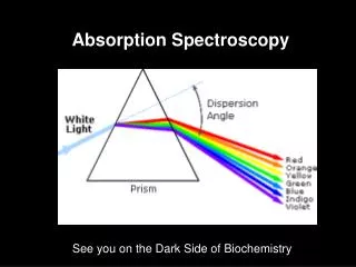
b) Wavelength Selectors: 1. Monochromator - separates frequencies (n) from polychromatic light. - allows only certain l’s to be selected and used. i.) Dispersing Monochromator: a) Prism: based on refraction of light and fact that different l’s have different values of refraction index (hi) in a medium.
Dispersion Curve: change in hi as a function of l Normally want to work in areas of normal dispersions for prisms. Anomalous dispersion occurs near where substance itself absorbs light.
h1sinq1 = h2sinq2 Recall Snell’s Law of Refraction Also, remember that no refraction occurs if light at normal or q1 = 0 So, light must hit prism at an angle. Most common is a 60o prism (glass or quartz).
ii.) Grating Monochromator: based on diffraction of light (constructive and deconstructive interference) a) Transmission Grating: groves or slits placed on a transparent material. Same as earlier example shown in diffraction discussion X n =2 Order of Interference (n): nl = d sinq n =1 Different l’s will have constructive interference at different points. Can select desired l by letting light at different points into instrument. n =0 n =1 Y
b) Reflection Grating: most commonly used - grooved surface with reflective coating (Al, Au, Pt) nl = d(sin i + sin r) Now, spacing of slits (d) is distance from one groove to next. Typically have 300-2000 grooves/mm. Constructive and deconstructive interference occurs because light travels different distances when reflected from each grating Angle at which constructive interference occurs is now given by: nl = d(sin i + sin r)
Example 5: A monochromator was equipped with an echellete grating of 2500 blazes per millimeter, where 2.0 cm of the grating was illuminated. At approximately 430 nm, what minimum wavelength difference could in theory be completely resolved by the instrument?
iii.) Two Types of Monochromators: a) Czerney-Turner Grating: Important Components: • Entrance slit • Collimating lens or mirror – makes radiation parallel before hitting dispersing element • Grating or Prism • Focusing Lens or mirror – to focus light of desired l on exit slit.
iii.) Two Types of Monochromators: b) Bunsen Prism: Important Components: • Entrance slit • Collimating lens or mirror – makes radiation parallel before hitting dispersing element • Grating or Prism • Focusing Lens or mirror – to focus light of desired l on exit slit.
iv.) Comparison of Gratings vs. Prisms: – increase size of either prism or grating will give better dispersion. – stray light can be removed with filters. – glass absorbs light l ≤ 350 nm
v.) Slits in the Monochromator: - need to be carefully made, since they control the range of l’s emerging from the monochromator. - typical slit widths are 0.01 – 2 mm are often adjustable. a) Band pass of the monochromator: range of l’s transmitted at the half-height of transmitted light band. Typical band pass : 20nm -0.5 nm for UV-vis instruments. - decrease slit size decrease band pass (good). - less undesired l’s, but less intensity (bad).
Two l’s can be resolved by the monochromator if they differ by 2 or more times the band pass. - l resolution is directly related to slit size.
a) Filter: Monochromators 1) Absorption Filters - material remove undesired l’s by absorbing them. - typically made from colored glass or dye suspended in gelatin between glass plates. - fixed l, much energy lost due to absorption. - cheap • wide range of l allowed through. • can combine filters with different l range. • typical band pass (30-250 nm). Effective bandwidth for two types of filters and the result of combining filters.
2) Interference Filters - made up of thin layers of metal and dielectric (eq. CaF2) material sandwiched between glass plates - dielectric material is of uniform, known thickness. - metal acts as partial mirror
2) Interference Filters As light enters, some goes through but some is reflected. The distance the light travels before it exits generates constructive and destructive interference on the other side of the filter. l’s transmitted through filter: Nl = 2dh • – refractive index d – thickness of dielectric N – integer l - wavelength Band pass can be 1-20nm. (narrow), but filter is fixed at given value as much intensity is lost due to reflection
vi.) Sample Cell: - Must be transparent at l used. • quartz or fused silica for UV (< 350 nm) • glass or plastic for visible - best if flat cells, with matched sample and reference cells. - many automated instruments have flow-through cells with temperature control. vii.) Detectors: a) earliest detectors were the eye or film. • now use devices that convert light to electrical signal b) for good detector want: • high sensitivity • good signal to noise ratio • constant response over l range of interest • signal µ light intensity • fast response • little or no signal in absence of light (dark current)
c) Many Types of Available Detectors for UV/VIS 1) photovoltaic cell (Barrier-Layer Cell) Process: light of sufficiently high energy passes through the thin transparent silver layer and hits selenium causing electrons to be released which move across barrier toward silver layer (electropositive) and collected at iron layer to neutralize selenium layer. • Current produced is proportional to photons hitting surface • Maximum response at 550 nm (10% at 350-750 nm ~ same as human eye). Advantage: cheap, rugged, no external power source, good for portable instruments. Disadvantage: not very sensitive, shows fatigue (decrease in response with continued illumination), difficult to amplify signal-small resistance (Ohm’s law: I=(V/R)).
2) Vacuum Phototube (Photoemission material) Process: - photoemission material (Cs2O) ejects an e- when “hit” with a photon (photoelectric effect). - potential of 90V across cathode(-) and anode(+). As light “hits” cathode, e- are emitted from cathode and attracted to anode. Produces current that can be measured. - current µnumber of photons. - smaller current then photovoltaic cell, but can be amplified because of larger resistance. - 90V difference sufficient to collect all e- produced (working at saturation). - various photoemission material (sensitive to certain photon l’s)
2) Vacuum Phototube Process (cont.): - various photoemission material (sensitive to certain photon l’s) - common to use phototubes in UV-Vis instruments • one tube for UV & most visible region, second tube for red end of spectrum. • some phototubes have “flat” regions throughout entire range (ex.128 Ga/As composite). • sometimes gas is present in tube. As e- collide with gas, more e- and ions produce results in an increase in current. Advantages: sensitive, signal easily amplified. Disadvantages: some dark current (from thermal e- emission & natural decay of 40K in glass housing
3) Photomultiplier tube (PMT) Dynodes – all covered with photoemissive material Process: a)light hits cathode and e- emitted. b) an emitted e- is attracted to electrode #1 (dynode 1), which is 90V more positive. Causes several more e- to be emitted. c)these e- are attracted to dynode 2, which is 90V more positive then dynode 1, emitting more e-. d) process continues until e- are collected at anode after amplification at 9 dynodes. e) overall voltage between anode and cathode is 900V. f) one photon produces 106 – 107 electrons. g) current is amplified and measured Advantages: very sensitive to low intensity, very fast response. Disadvantages: need high voltage power supply, intense light damages
4) Silicon Diode or Photodiode detectors Semiconductor material – conducts current only under certain conditions Reverse-bias: no current flows free electrons inside the N-type material need some extra energy to overcome the repulsion of the P-type's acceptor atoms. • Light shining on the silicon diode provides the energy needed for the electrons to travel into the P region. - Flow of current is related to intensity of light.
4) Silicon Diode or Photodiode detectors • Not very sensitive, but useful in Vidicon Tubes • Vidicon tubes can be used for 1 & 2 dimensional detection • Detect all the l’s along the focal plane of an instrument A vidicon tube contains many silicon diodes each insulated from each other (~ 8mm apart). The e- gun or light source sweeps the P-region and charges the diodes. (Television)
vii.) Single and Double Beam Instruments: - To determine absorbance both Po and P must be measured. - depends on: • intensity of source • slit width & l of monochromator • reflectance of the cell • sensitivity of the detector Absorbance (A) = log10 Po/P
Process for a Single Beam Spectrometer: a) Po is measured with solvent in the cell b) P, blank everything except compound to be analyzed - spectrophotometer is adjusted to read 100%T or 0% A. - 0%T or ¥A is set by blocking the light beam (P=0) - settings may change over a period of minutes (drift) • change in light source intensity - settings are wavelength dependent Spectronic 20 Schematic of Spectronic 20
Single beam spectrophotometer (340-625nm) other phototube goes to 950 nm (20 nm band pass) -Reference phototube electronically adjusts for changes in source intensity - The l control turns the grating. - The 0%T adjust sets the meter to 0%T when the occluder blocks the light beam. • The 100% T adjusts moves a V-shaped slot into or out of the light beam so the meter reads 100%T Advantages: cheap, rugged. Disadvantages: must readjust 100%T at every l and periodically check for drift, cell is round so path length can vary if don’t have cell aligned the same each time
Double Beam Spectrometer Decrease/Eliminates Single Beam Problems Schematic of Hitachi 100-60 Selector mirror or beam chopper: mirrors which rotate at 60 cps, reflecting the light alternatively to the reference and sample cells All light is combined and goes to a single PMT. Output of PMT is 60 cps square wave. Po and P are measured alternatively at a rate of 60 times per second. Advantages:l scanning, little drift – only one PMT. Disadvantages: more complex and expensive