Download
1 / 82
820 likes | 1.05k Views
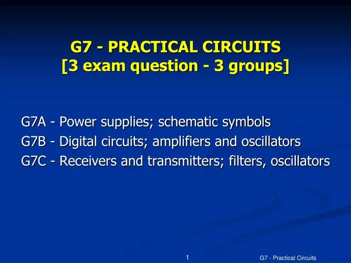
G7 - PRACTICAL CIRCUITS [3 exam question - 3 groups]. G7A - Power supplies; schematic symbols G7B - Digital circuits; amplifiers and oscillators G7C - Receivers and transmitters; filters, oscillators. Half Wave Power Supply. Regulated Power Supply.

E N D
G7 - PRACTICAL CIRCUITS [3 exam question - 3 groups] • G7A - Power supplies; schematic symbols • G7B - Digital circuits; amplifiers and oscillators • G7C - Receivers and transmitters; filters, oscillators G7 - Practical Circuits
Half Wave Power Supply G7 - Practical Circuits
Regulated Power Supply The transformer converts 120 volt AC line voltage to 12.6 volts AC. The bridge rectifier feeds pulsed DC into the large capacitor which filters the power to DC. The 7812 voltage regulator takes the DC input and creates a stable 12 volt DC output. The final capacitor removes any ripple from the regulator and stabilizes the output. G7 - Practical Circuits
G7A01 What safety feature does a power-supply bleeder resistor provide? • A. It acts as a fuse for excess voltage • B. It discharges the filter capacitors • C. It removes shock hazards from the induction coils • D. It eliminates ground-loop current G7 - Practical Circuits
G7A01 What safety feature does a power-supply bleeder resistor provide? • A. It acts as a fuse for excess voltage • B. It discharges the filter capacitors • C. It removes shock hazards from the induction coils • D. It eliminates ground-loop current G7 - Practical Circuits
G7A02 Which of the following components are used in a power-supply filter network? • A. Diodes • B. Transformers and transducers • C. Quartz crystals • D. Capacitors and inductors G7 - Practical Circuits
G7A02 Which of the following components are used in a power-supply filter network? • A. Diodes • B. Transformers and transducers • C. Quartz crystals • D. Capacitors and inductors G7 - Practical Circuits
G7A03 What is the peak-inverse-voltage across the rectifiers in a full-wave bridge power supply? • A. One-quarter the normal output voltage of the power supply • B. Half the normal output voltage of the power supply • C. Double the normal peak output voltage of the power supply • D. Equal to the normal peak output voltage of the power supply G7 - Practical Circuits
G7A03 What is the peak-inverse-voltage across the rectifiers in a full-wave bridge power supply? • A. One-quarter the normal output voltage of the power supply • B. Half the normal output voltage of the power supply • C. Double the normal peak output voltage of the power supply • D. Equal to the normal peak output voltage of the power supply G7 - Practical Circuits
G7A04 What is the peak-inverse-voltage across the rectifier in a half-wave power supply? • A. One-half the normal peak output voltage of the power supply • B. One-half the normal output voltage of the power supply • C. Equal to the normal output voltage of the power supply • D. Two times the normal peak output voltage of the power supply G7 - Practical Circuits
G7A04 What is the peak-inverse-voltage across the rectifier in a half-wave power supply? • A. One-half the normal peak output voltage of the power supply • B. One-half the normal output voltage of the power supply • C. Equal to the normal output voltage of the power supply • D. Two times the normal peak output voltage of the power supply G7 - Practical Circuits
G7A05 What portion of the AC cycle is converted to DC by a half-wave rectifier? • A. 90 degrees • B. 180 degrees • C. 270 degrees • D. 360 degrees G7 - Practical Circuits
G7A05 What portion of the AC cycle is converted to DC by a half-wave rectifier? • A. 90 degrees • B. 180 degrees • C. 270 degrees • D. 360 degrees G7 - Practical Circuits
G7A06 What portion of the AC cycle is converted to DC by a full-wave rectifier? • A. 90 degrees • B. 180 degrees • C. 270 degrees • D. 360 degrees G7 - Practical Circuits
G7A06 What portion of the AC cycle is converted to DC by a full-wave rectifier? • A. 90 degrees • B. 180 degrees • C. 270 degrees • D. 360 degrees G7 - Practical Circuits
G7A07 What is the output waveform of an unfiltered full-wave rectifier connected to a resistive load? • A. A series of DC pulses at twice the frequency of the AC input • B. A series of DC pulses at the same frequency as the AC input • C. A sine wave at half the frequency of the AC input • D. A steady DC voltage G7 - Practical Circuits
G7A07 What is the output waveform of an unfiltered full-wave rectifier connected to a resistive load? • A. A series of DC pulses at twice the frequency of the AC input • B. A series of DC pulses at the same frequency as the AC input • C. A sine wave at half the frequency of the AC input • D. A steady DC voltage G7 - Practical Circuits
G7A08 Which of the following is an advantage of a switch-mode power supply as compared to a linear power supply? • A. Faster switching time makes higher output voltage possible • B. Fewer circuit components are required • C. High frequency operation allows the use of smaller components • D. All of these choices are correct G7 - Practical Circuits
G7A08 Which of the following is an advantage of a switch-mode power supply as compared to a linear power supply? • A. Faster switching time makes higher output voltage possible • B. Fewer circuit components are required • C. High frequency operation allows the use of smaller components • D. All of these choices are correct G7 - Practical Circuits
G7A09 Which symbol in figure G7-1 represents a field effect transistor? • A. Symbol 2 • B. Symbol 5 • C. Symbol 1 • D. Symbol 4 G7 - Practical Circuits
G7A09 Which symbol in figure G7-1 represents a field effect transistor? • A. Symbol 2 • B. Symbol 5 • C. Symbol 1 • D. Symbol 4 G7 - Practical Circuits
G7A10 Which symbol in figure G7-1 represents a Zener diode? • A. Symbol 4 • B. Symbol 1 • C. Symbol 11 • D. Symbol 5 G7 - Practical Circuits
G7A10 Which symbol in figure G7-1 represents a Zener diode? • A. Symbol 4 • B. Symbol 1 • C. Symbol 11 • D. Symbol 5 G7 - Practical Circuits
G7A11 Which symbol in figure G7-1 represents an NPN junction transistor? • A. Symbol 1 • B. Symbol 2 • C. Symbol 7 • D. Symbol 11 G7 - Practical Circuits
G7A11 Which symbol in figure G7-1 represents an NPN junction transistor? • A. Symbol 1 • B. Symbol 2 • C. Symbol 7 • D. Symbol 11 G7 - Practical Circuits
G7A12 Which symbol in Figure G7-1 represents a multiple-winding transformer? • A. Symbol 4 • B. Symbol 7 • C. Symbol 6 • D. Symbol 1 G7 - Practical Circuits
G7A12 Which symbol in Figure G7-1 represents a multiple-winding transformer? • A. Symbol 4 • B. Symbol 7 • C. Symbol 6 • D. Symbol 1 G7 - Practical Circuits
G7A13 Which symbol in Figure G7-1 represents a tapped inductor? • A. Symbol 7 • B. Symbol 11 • C. Symbol 6 • D. Symbol 1 G7 - Practical Circuits
G7A13 Which symbol in Figure G7-1 represents a tapped inductor? • A. Symbol 7 • B. Symbol 11 • C. Symbol 6 • D. Symbol 1 G7 - Practical Circuits
Digital Gates AND NAND A and B are inputs to the gates with Q being the output value. OR NOR Notice the NAND and NOR gates are exactly the opposite of their counterparts. The AND or OR function is performed and the result is inverted or NOTed. G7 - Practical Circuits
G7B01 Complex digital circuitry can often be replaced by what type of integrated circuit? • A. Microcontroller • B. Charge-coupled device • C. Phase detector • D. Window comparator G7 - Practical Circuits
G7B01 Complex digital circuitry can often be replaced by what type of integrated circuit? • A. Microcontroller • B. Charge-coupled device • C. Phase detector • D. Window comparator G7 - Practical Circuits
G7B02 Which of the following is an advantage of using the binary system when processing digital signals? • A. Binary "ones" and "zeros" are easy to represent with an "on" or "off" state • B. The binary number system is most accurate • C. Binary numbers are more compatible with analog circuitry • D. All of these choices are correct G7 - Practical Circuits
G7B02 Which of the following is an advantage of using the binary system when processing digital signals? • A. Binary "ones" and "zeros" are easy to represent with an "on" or "off" state • B. The binary number system is most accurate • C. Binary numbers are more compatible with analog circuitry • D. All of these choices are correct G7 - Practical Circuits
G7B03 Which of the following describes the function of a two input AND gate? • A. Output is high when either or both inputs are low • B. Output is high only when both inputs are high • C. Output is low when either or both inputs are high • D. Output is low only when both inputs are high G7 - Practical Circuits
G7B03 Which of the following describes the function of a two input AND gate? • A. Output is high when either or both inputs are low • B. Output is high only when both inputs are high • C. Output is low when either or both inputs are high • D. Output is low only when both inputs are high G7 - Practical Circuits
G7B04 Which of the following describes the function of a two input NOR gate? • A. Output is high when either or both inputs are low • B. Output is high only when both inputs are high • C. Output is low when either or both inputs are high • D. Output is low only when both inputs are high G7 - Practical Circuits
G7B04 Which of the following describes the function of a two input NOR gate? • A. Output is high when either or both inputs are low • B. Output is high only when both inputs are high • C. Output is low when either or both inputs are high • D. Output is low only when both inputs are high G7 - Practical Circuits
G7B05 How many states does a 3-bit binary counter have? • A. 3 • B. 6 • C. 8 • D. 16 G7 - Practical Circuits
G7B05 How many states does a 3-bit binary counter have? • A. 3 • B. 6 • C. 8 • D. 16 G7 - Practical Circuits
G7B06 What is a shift register? • A. A clocked array of circuits that passes data in steps along the array • B. An array of operational amplifiers used for tri state arithmetic operations • C. A digital mixer • D. An analog mixer G7 - Practical Circuits
G7B06 What is a shift register? • A. A clocked array of circuits that passes data in steps along the array • B. An array of operational amplifiers used for tri state arithmetic operations • C. A digital mixer • D. An analog mixer G7 - Practical Circuits
G7B07 What are the basic components of virtually all sine wave oscillators? • A. An amplifier and a divider • B. A frequency multiplier and a mixer • C. A circulator and a filter operating in a feed-forward loop • D. A filter and an amplifier operating in a feedback loop G7 - Practical Circuits
G7B07 What are the basic components of virtually all sine wave oscillators? • A. An amplifier and a divider • B. A frequency multiplier and a mixer • C. A circulator and a filter operating in a feed-forward loop • D. A filter and an amplifier operating in a feedback loop G7 - Practical Circuits
G7B08 How is the efficiency of an RF power amplifier determined? • A. Divide the DC input power by the DC output power • B. Divide the RF output power by the DC input power • C. Multiply the RF input power by the reciprocal of the RF output power • D. Add the RF input power to the DC output power G7 - Practical Circuits
G7B08 How is the efficiency of an RF power amplifier determined? • A. Divide the DC input power by the DC output power • B. Divide the RF output power by the DC input power • C. Multiply the RF input power by the reciprocal of the RF output power • D. Add the RF input power to the DC output power G7 - Practical Circuits
G7B09 What determines the frequency of an LC oscillator? • A. The number of stages in the counter • B. The number of stages in the divider • C. The inductance and capacitance in the tank circuit • D. The time delay of the lag circuit G7 - Practical Circuits
G7B09 What determines the frequency of an LC oscillator? • A. The number of stages in the counter • B. The number of stages in the divider • C. The inductance and capacitance in the tank circuit • D. The time delay of the lag circuit G7 - Practical Circuits
G7B10 Which of the following is a characteristic of a Class A amplifier? • A. Low standby power • B. High Efficiency • C. No need for bias • D. Low distortion G7 - Practical Circuits
G7B10 Which of the following is a characteristic of a Class A amplifier? • A. Low standby power • B. High Efficiency • C. No need for bias • D. Low distortion G7 - Practical Circuits

![G6 - CIRCUIT COMPONENTS [3 exam question - 3 groups]](https://cdn0.slideserve.com/528131/g6-circuit-components-3-exam-question-3-groups-dt.jpg)