Download
1 / 35
350 likes | 411 Views
Electronics and Signals. Chapter 4. Parts of an Atom. nucleus - the center part of the atom, formed by neutrons and protons protons - particles have a positive charge, and along with neutrons, form the nucleus

E N D
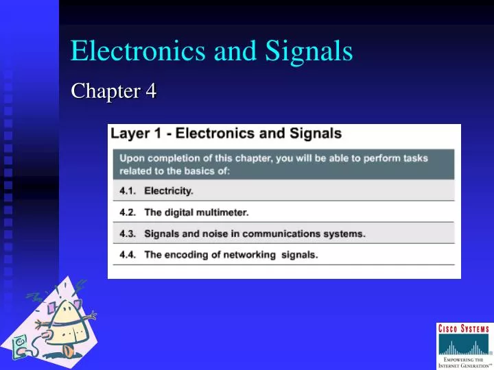
Electronics and Signals Chapter 4
Parts of an Atom • nucleus - the center part of the atom, formed by neutrons and protons • protons - particles have a positive charge, and along with neutrons, form the nucleus • neutrons – particleshave no charge(neutral), and alongwith protons, form the nucleus • electrons - particles have a negative charge, and orbit the nucleus
Types of Electrical Materials • insulators—high resistance to electrical current • plastic, glass, air, wood, paper, rubber • conductors—conducts the flow of electrons • Copper, silver, gold • semiconductors—control the flow of electrons • carbon, silicon
Measuring Electricity • Voltage (V)—electrical force or pressure that occurs when electrons and protons are separated • The force that is created pushes toward the opposite charge and away from the like charge. • Voltage can also be created by friction (static electricity), by magnetism (electric generator), or by light (solar cell). • unit of measurement is VOLT
Measuring Electricity • Current (I)—the measurement of electron flow in an electrical circuit • unit of measurement is AMPERE (amp) • Resistance (R)—amount of opposition to current • unit of measurement is the OHM ()
Measuring Electricity Electricity is brought to your home, school, and office by power lines. The power lines carry electricity in the form of alternating current (AC). Another type of current, called direct current (DC) can be found in flashlight batteries, car batteries, and as power for the microchips on the motherboard of a computer. It is important to understand the difference between these two types of current.
Measuring Electricity • Alternating Current (AC) • flows in two directions • Direct Current (DC) • flows in one direction only • Impedance--(Z)—unit of measurement () • total opposition to current flow (due to AC and DC voltages) • resistance--generally used when referring to DC voltages
Measuring Electricity • current flows through closed loopscalled circuits • These circuits must be composed of conducting materials and have sources of voltage. • The three required parts of an electrical circuit are source or battery, complete path, load or resistance. • Voltage causes current to flow while resistance and impedance oppose it.
Measuring Electricity • For AC and DC electrical systems, the flow of electrons is always from a negatively charged source to a positively charged source. • For the controlled flow of electrons to occur, a complete circuit is required. • Electrical current generally follows the path of least resistance.
Measuring Electricity • Because metals such as copper provide little resistance, they frequently are used as conductors for electrical current. • Materials such as glass, rubber, and plastic provide more resistance; they are not good conductors and are generally used as insulators.
Measuring Electricity The purpose of connecting the safety ground to exposed metal parts of computing equipment is to prevent such metal parts from becoming energized with a hazardous voltage from a wiring fault inside the device.
Using a Multimeter to Make Resistance Measurements A multimeter can use used to measure • voltage • resistance • continuity
Using a Multimeter to Make Resistance Measurements • If you intentionally make a path into a low-resistance path for use by two connected electrical devices, then the path has continuity. • If a path is made unintentionally into a low-resistance path, then it is called a short circuit. • The unit of measurement for both is the OHM (). • Continuity refers to the level of resistance of a path.
Using a Multimeter to Make Resistance Measurements • You can perform measurements on the following: • CAT 5 cable • Terminated CAT 5 cable • Terminated coaxial cable • Telephone wire • CAT 5 jacks • Switches • Wall outlets
Using a Multimeter to Make Voltage Measurements • Two types of voltage measurements exist: DC and AC. • The meter must be set to DC when measuring DC voltages. This includes the following: • batteries • outputs of computer power supplies • solar cells • DC generators
Using a Multimeter to Make Voltage Measurements • Two types of voltage measurements exist: DC and AC. • The meter must be set to AC when you measure AC voltages. • If you measure a wall socket, you must assume that line voltage is present. • Line voltage is 120 V AC in the US and 220 V AC in most other places around the world.
Signals and Noise in Communication Systems • The term signal refers to a desired electrical voltage, light pattern, or modulated electromagnetic wave. • Signals can be created as • electrical pulses that travel over copper wire • pulses of light that travel through strands of glass or plastic • radio transmissions that travel over the airwaves • as laser or satellite transmissions • as infrared pulse
Signals and Noise in Communication Systems • Two main types of signaling • analog • change gradually and continuously (will have a continuously varying voltage-versus-time graph) • typical of things in nature • used widely in telecommunications for more than 100 years • digital • change one state to another almost instantaneously, without stopping at an in-between state • discrete or jumpy • typical of technology instead of nature
Measuring Analog Signals • Analog signals are measured in cycles, with one cycle representing the change from high to low and back again. • Three characteristics are measured: • amplitude • frequency • phase
Digital and Analog Signaling • Digital signaling is the most appropriate format for transmitting computer data, and most networks use digital signaling methods for that reason. • Because it is a simpler technology, digital signaling has some advantages over analog: • generally less expensive to make digital equipment • generally less vulnerable to errors caused by interference because the discrete state of on and off is not as easily affected by a small distortion as is a continuous waveform
Digital and Analog Signaling • Analog signals also have advantages: • Signals can be easily mutilplexed; that is signals can be combined to increase bandwidth. • Signals are less vulnerable to the problem of attenuation (signal loss due to surroundings) because of distance so they can travel farther without becoming too weak for reliable transmission. However, when an analog signal is amplified, the noise is amplified with the signal. • Digital connectivity solutions generally offer better security, faster performance, and higher reliability.
Simplex, Half-Duplex, and Full-Duplex Transmission • Simplex Transmission • Unidirectional—signal travels in only one direction • Television is an example. • Half-Duplex Transmission • Signal can travel in both directions but not at the same time. • Full-Duplex Transmission • Signal can travel in both directions at the same time.
Baseband and Broadband • The entire capacity of an Ethernet cable is used for transmitting the data in one channel. • This makes Ethernet a BASEBAND technology. • A channel is an allocated portion of the media’s available bandwidth. • The signal has the benefit of having the entire bandwidth to itself. • BASEBAND is usually associated with digital signaling (although it can be used with analog). • Most computer communications are baseband. • BASEBAND signal is bidirectional; the signal can flow both ways so you can transmit and receive on the same cable.
Baseband and Broadband • BROADBAND technologies allow for dividing the capacity of a link into two or more channels, each of which can carry a different signal. • All channels can send simultaneously. • ISDN is an example of BROADBAND technology because multiple signals can be carried over separate channels on a single wire. • DSL is another example of a BROADBAND technology because data and voice can travel simultaneously over the same line.
Signaling and Communications Problems • Propagation • travel time; speed depends upon medium • As data transmission rates increase, you must sometimes take into account the amount of time it takes the signal to travel. • Attenuation • loss of signal over distance due to surroundings • can affect a network because it limits the length of network cabling over which you can send a message
Signaling and Communications Problems • Reflection • caused by discontinuities in the medium • occurs in electrical signals; can be a result of kinks in cable or poorly terminated cables • networks should have a specific impedance to match the electrical components in the NICs • The result of impedance mismatch is reflected energy.
Signaling and Communications Problems Noise • unwanted additions to optical/electromagnetic signals • Crosstalk—electrical noise from other wires in a cable • EMI (electromagnetic interference) can be caused by electric motors. • Cancellation of signals can be avoided through the twisting of wire pairs to provide self-shielding within the network media.
Signaling and Communications Problems • Timing problem • Dispersion—signal broadens in time • can be fixed by proper cable design, limiting cable lengths, and finding the proper impedance • Jitter—source and destination not synchronized • can be fixed through hardware and software including protocols • Latency—delay of network signal
Signaling and Communications Problems • Collisions • occurs when two bits from different communicating computers are on a shared medium at the same time • excessive collisions can slow the network
Encoding Networking Signals • Encoding means to convert the binary data into a form that can travel on a physical communications link such as an electrical pulse on a wire, a light pulse on an optical fiber, or an electromagnetic wave in space. • two methods for encoding • TTL—high signals or low signals • Manchester—more complex and more immune to noise and better at remaining synchronized (includes NRZs and 4B/5B
Encoding Networking Signals • Modulation means using the binary data to manipulate an analog wave. • taking a wave and changing it so that it carries information • AM • FM • PM
Lab Activities Check Your Understanding Journal