Download
1 / 22
220 likes | 415 Views
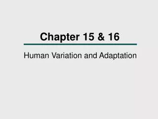
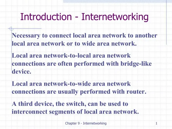
Chapter 15&16 Internetworking. Internetwork Structure & Terms Internetworking Architecture Features Connection/ Connectionless Architecture Fragmentation & Reassembly Internet Protocol & Services IP Addressing Subnetting Routing Protocols in IP. Internetworking Terms.

E N D
Chapter 15&16 Internetworking • Internetwork Structure & Terms • Internetworking Architecture Features • Connection/Connectionless Architecture • Fragmentation & Reassembly • Internet Protocol & Services • IP Addressing • Subnetting • Routing Protocols in IP
Internetworking Terms • An internet • Collection of communications networks interconnected by bridges and/or routers • The Internet - note upper case I • The global collection of thousands of individual machines and networks • Intranet: Corporate internet operating within the organization • Isolated or may have links to Internet • End System (ES): Device attached to one of the networks of an internet • Supports end-user applications or services • Intermediate System (IS): Device used to connect two networks • Permits communication between end systems attached to different networks • Bridge: IS used to connect two or more LANs using similar LAN protocols • Address filter passing on packets to the required network only • Operated at OSI layer 2 (Data Link) • Router: Connects two or more (possibly dissimilar) networks • Uses internet protocol present in each router and end system • Operated at OSI Layer 3 (Network)
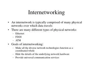
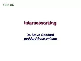
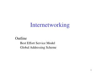
NSFNET backbone Stanford ISU BARRNET MidNet … regional regional Westnet regional Berkeley PARC UNL KU UNM NCAR UA Internet Structure Recent Past (1990) End user Service Provider AS (autonomous system): each with its own idea of routing and metrics defining. An AS is administered independently.
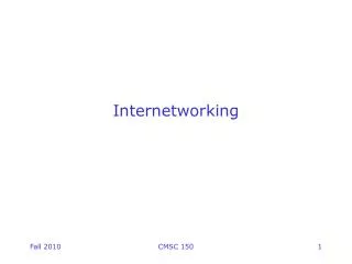
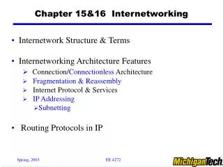
Large corporation “ ” Consumer ISP Peering point Backbone service provider Peering point Consumer ” ISP “ “ Consumer ISP ” Large corporation Small corporation Internet Structure Today Service provider networks
Internetworking Protocols in TCP/IP Suite • Requirements of Internetworking • Link between networks: Minimum physical and link layer • Routing and delivery of data between processes on different networks • Accounting services and status info • Independent of constituting network architectures
Internetworking Architecture Features • Accommodate difference among networks • Addressing: global network addressing must be provided • Packet size -> fragmentation • Timeouts: longer timeout for delivery across multiple networks • Error recovery: independent to individual network error rec. cap. • Status reporting • Routing • Connection based or connectionless
Architectural Approaches • Connection oriented: Assume that each network is connection oriented • IS connect two or more networks: IS appear as DTE to each network • Logical connection set up between DTEs (Data Terminal Equipment) • Concatenation of logical connectionsacross networks • Individual network virtual circuits joined by IS • May require enhancement of local network services (e.g. 802 or FDDI) • IS performs Relaying & Routing functions • Connectionless • Corresponds to datagram mechanism in packet switched network • Each PDU treated separately • Network layer protocol common to all DTEs and routers • Known generically as the internet protocol • Internet Protocol (RFC 791 -> IETF) • One such internet protocol developed for ARPANET • Lower layer protocol needed to access particular network
Connectionless Internetworking • Advantages • Flexibility • Robust • No unnecessary overhead • Unreliable • Not guaranteed delivery • Not guaranteed order of delivery: Packets can take different routes • Reliability is responsibility of next layer up (e.g. TCP) • Design Issues • Routing • Datagram lifetime • Fragmentation & re-assembly • Error control • Flow control
Routing • End systems & routers maintain routing tables to indicate next router to which datagram should be sent • Static: May contain alternative routes • Dynamic: Flexible response to congestion and errors • Source routing • Source specifies route as sequential list of routers to be followed
Datagram Lifetime • Datagrams could loop indefinitely • Consumes resources • Transport protocol may need upper bound on datagram life • Datagram marked with lifetime • Time-To-Live (TTL) field in IP • Once lifetime expires, datagram discarded (not forwarded) • Hop count: a simple way to implement TTL • Decrement TTL on passing through at each router • True time count: global clocking mechanism needed • Need to know how long since last router
H1 H8 TCP TCP R1 R2 R3 IP IP IP IP IP FDDI PPP ETH ETH ETH FDDI PPP ETH Fragmentation and Reassembly • Each network has some MTU (Maximum Transmission Unit) • e.g., Ethernet:1500B; FDDI:4500B, IP: 65,535B • When to re-assemble • At destination (preferred) • Results in packets getting smaller as data traverses internet • Intermediate re-assembly • Need large buffers at routers • Buffers may fill with fragments • All fragments must go through same router • Inhibits dynamic routing
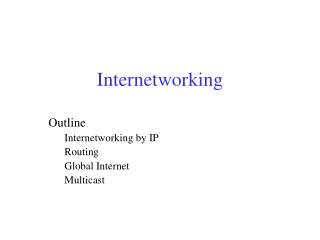
Start of header Ident = x Offset = 0 0 Rest of header 1400 data bytes Start of header Ident = x 1 Offset = 0 Rest of header 512 data bytes Start of header Ident = x 1 Offset = 512 Rest of header 512 data bytes Start of header Ident = x 0 Offset = 1024 Rest of header 376 data bytes Example Note: Offset field counts 8-byte units of data, not individual bytes
Error & Flow Control • Error Control • Not guaranteed delivery • Router should attempt to inform source if packet discarded • Source may modify transmission strategy after the discard • May inform high layer protocol • Datagram identification needed • Flow Control (? Congestion Control) • Allows routers and/or stations to limit rate of incoming data • The mechanism is limited in connectionless systems • Send flow control packets: Requesting reduced flow
Internet Protocol (IP) • Part of TCP/IP: Used by the Internet • Specifies interface with higher layer: e.g. TCP • Specifies protocol format and mechanisms • IP Services can be described by • Primitives to specify functions to be performed: Implementation dependent • Send: Request transmission of data unit • Deliver: Notify user of arrival of data unit • Parameters: Used to pass data and control info • Source/Destination address • Protocol: Recipient e.g. TCP • Type of Service (TOS): Specify QoS of data unit during transmission through networks • Identification: combined with source, destination address and user protocol • Uniquely identifies PDU • Needed for re-assembly and error reporting
IP Services Parameters (Con’t) • Time to live (TTL): Send only • Data length • Option data : options requested by the IP user • Security • Source routing • Route recording • Stream identification • Timestamping • User data • Carries user data from next layer up • Integer multiple of 8 bits long (octet) • Max length of datagram (header plus data) 65,535 octets
IP Header • Version: Currently 4 • IP v6 – next generation • Internet header length (IHL):In 32 bit words • Including options • Type of service (TOS) • Total length : Of datagram, in octets • Identification:Sequence number • Used with addresses and user protocol to identify datagram uniquely • Flags: More bit • Don’t fragment • Fragmentation offset • Time to live (TTL) • Protocol: Next higher layer to receive data field at destination • Header checksum • Reverified and recomputed at each router • 16 bit ones complement sum of all 16 bit words in header • Set to zero during calculation • Source/Destination address • Options • Padding: To fill to multiple of 32 bits long
7 24 A: 0 Network Host 14 16 B: 1 0 Network Host 21 8 C: 1 1 0 Network Host Network 1 (Ethernet) H7 R3 H8 H2 H1 H3 Network 4 Network 2 (Ethernet) (point-to-point) R1 R2 H4 Network 3 (FDDI) Global IP Addresses • Properties • globally unique • hierarchical: network + host • Dot Notation • 10.3.2.4 • 128.96.33.81 • 192.12.69.77 Note: It is more precise to think of IP address as belonging to interfaces than to hosts Class D(start 1110) address specify a multicast group Class E (start 1111): reserved for future use H5 H6
Network number Host number Class B address Bitwise AND 111111111111111111111111 00000000 Subnet mask (255.255.255.0) Network number Subnet ID Host ID Subnetted address Subnetting & Subnet Mask • Problem: Assigning one network #per physical network, not only used up the IP address space very fast, but also increase the burden of routing. • Solution: Add another level to address/routing hierarchy: subnet assign a single IP network # and allocate the IP addresses with that network # to several physical networks • Subnet masksdefine variable partition of host part
Subnet mask: 255.255.255.128 A host connected to this subnetwork could have an IP address between 128.96.34.1 and 128.96.34.127 Subnet number: 128.96.34.0 128.96.34.15 128.96.34.1 H1 R1 Subnet mask: 255.255.255.128 128.96.34.130 Subnet number: 128.96.34.128 A host connected to this subnetwork could have an IP address between 128.96.34.129 and 128.96.34.255 128.96.34.139 128.96.34.129 H2 R2 H3 128.96.33.1 128.96.33.14 A host connected to this subnetwork could have an IP address between 128.96.33.1 and 128.96.33.255 Subnet mask: 255.255.255.0 Subnet number: 128.96.33.0 Subnet Example Bitwise AND of the host IP address & subnet mask = subnet number A single class B (128.96.*.*) address shared by several physical network
IP Versions • IP v 1-3 defined and replaced • IP v4 - current version • IP v5 - streams protocol • IP v6 - replacement for IP v4 • Under development it is called IPng (Next Generation) • Why IP v6 • Address space exhaustion • Two level addressing (network and host) wastes space • Growth of networks and the Internet • Single address per host • Requirements for new types of service
Autonomous Systems (AS) • Set of routers and networks managed by single organization • Group of routers exchange information • Each AS with its own idea of routing and metrics defining. An AS is administered independently.
Routing Protocols • Routing Information • About topology and delays in the internet • Routing Algorithm • Used to make routing decisions based on information • Interior Router Protocol: Passes routing information between routers within AS • Routing algorithms and tables may differ between different AS • IRP needs detailed model • e.g., RIP (using Bellman-Ford algorithm) • e.g., OSPF ( using Dijkstra’s algorithm) • Exterior router protocol (ERP): Routers need some info about networks outside their AS: e.g. BGP in Internet • supports summary information on reachability