Download
1 / 21
210 likes | 296 Views
Microbunching and CSR experiments at BNL’s Source Development Lab. William S. Graves ICFA CSR Workshop Berlin, Jan., 2002. SDL Facility. 50 m. 1.6 cell gun with copper cathode. IR interferometer. Bunch compressor. Bend. Undulators. Bend. Linac tanks. 75 MeV. 5 MeV. Time domain

E N D
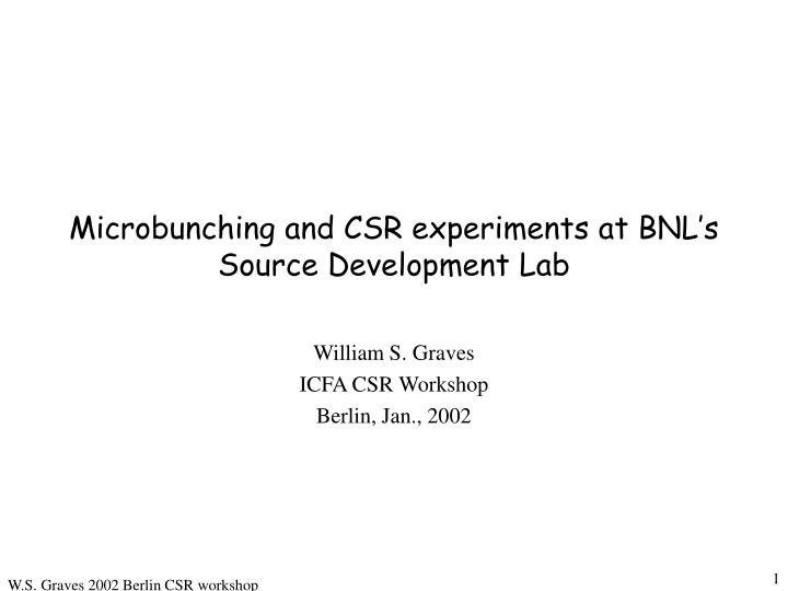
Microbunching and CSR experiments at BNL’s Source Development Lab William S. Graves ICFA CSR Workshop Berlin, Jan., 2002
SDL Facility 50 m 1.6 cell gun with copper cathode IR interferometer Bunch compressor Bend Undulators Bend Linac tanks 75 MeV 5 MeV Time domain measurements Dump Dump 200 MeV 30 mJ, 100 fs Ti:Sapphire laser Goal is to reach deep UV wavelength using High Gain Harmonic Generation (HGHG) process seeded by conventional laser for full longitudinal coherence. Currently commissioning undulator with SASE at 400 nm.
DUVFEL Accelerator 25 m 1.6 cell gun with copper cathode Coherent IR detector Matching triplet Chicane Slice quad scan 3m S-band tanks Bend Tank 4 Tank 3 Tank 2 Tank 1 197 MeV 137 MeV 77 MeV 40 MeV 5 MeV Pop 14 YAG OTR screen can intercept dipole radiation and not beam Kly C Kly B Kly A 45 MW Thompson Klystrons 30 mJ, 100 fs Ti:Sapphire laser
SDL data from 1/8/2002 File: rfplus01, RMS length = 0.763 ps 35 30 25 20 Current (A) 15 File: CC010822, RMS length = 1.26 ps 0.18 10 0.16 File: lasera, Hor. RMS width = 0.695 mm 1 5 0.14 0.9 0.12 0 0.8 -2.5 -2 -1.5 -1 -0.5 0 0.5 1 1.5 2 2.5 Detector (mV) 0.1 Time (ps) 0.7 0.08 Intensity (A.U.) 0.6 0.06 0.5 0.04 0.4 0.02 0.3 0.2 0 -3 -2 -1 0 1 2 3 0.1 Time (ps) File: lasera, Ver. RMS width = 0.64 mm 0 -2 -1.5 -1 -0.5 0 0.5 1 1.5 2 1 Hor. Position (mm) 0.9 0.8 0.7 Intensity (A.U.) 0.6 0.5 0.4 0.3 0.2 0.1 0 -2 -1.5 -1 -0.5 0 0.5 1 1.5 2 Ver. Position (mm) UV laser virtual cathode image UV laser time profile Ebeam time profile Technical Data Gun energy: 5.37 MeV Gradient: 114 MV/m. E-beam parameters at chicane entrance: Emitnx = 1.08 um, Alphax = -0.78, Betax = 3.1 m, Emitny = 1.30 um, Alphay = -1.78, Betay = 3.1 m Initial phase: leading edge of beam at 30 degrees from phase of zero crossing. RMS laser size on cathode: 0.695 mm hor, 0.640 mm ver. Charge: 50 pC Pop14: pixel size: 28.8 um (all electron beam profiles are from pop14), image size: 640 X 480, dispersion: 1.1 m Cathode pix.el size: 13.75 um Linac gradient approx. 11.89 MV/m. Final max energy: 76.7 MeV Chicane angle at 50 A, 75 MeV: .2097 rad Horizontal projection Vertical projection
Energy spectrum measurement L2 phase varies, amplitude constant L1 phase = 0, amplitude constant L4 off L3 off Chicane varies from 0 cm < R56 < 10.5 cm L4 L3 L2 L1 RF zero-phase time profile L4 phase = -90, amplitude varies (adds known chirp) L3 phase = +90, amplitude varies (removes chirp from L2) L2 phase varies, amplitude constant L1 phase = 0, amplitude constant Chicane varies from 0 cm < R56 < 10.5 cm L4 L3 L2 L1 T. Smith method time profile L2 phase varies, amplitude constant L1 phase = 0, amplitude constant L3 off L4 phase = -90, amplitude ~ 1/R56 Chicane set for R56 ~ 9 cm L4 L3 L2 L1
RMS width = 90.1 keV RMS width = 16.6 keV RMS width = 74.6 keV RMS width = 151 keV RMS width = 188 keV 74.2 74.4 74.6 74.8 75 75.2 Energy (MeV) 75.6 75.8 76.2 76.4 76 76.2 76.6 76.4 76.8 76.6 77 77.2 72.2 72.4 72.6 72.8 73 73.2 Energy (MeV) Energy (MeV) 74.4 74.6 74.8 75 75.2 75.4 Energy (MeV) Energy (MeV) Energy spectrum measurement with chicane off. L2 phase varies, amplitude constant L1 phase = 0, amplitude constant L4 off L3 off R56 = 0 cm L4 L3 L2 L1 Pop 14 YAG Images from Pop 14 at varying L2 phase and and chicane off. Energy spectrum is modified by CSR in chicane. L2 = -16 deg. L2 = -8 deg. L2 = 0 deg. L2 = +16 deg. L2 = +28 deg.
Energy profiles at many L2 phases L2 = -28 deg. L2 = -24 deg. L2 = -16 deg. L2 = -8 deg. L2 = 0 deg. L2 phase varying. Chicane, L3, and L4 off. L2 = -32 deg. L2 = -20 deg. L2 = -12 deg. L2 = -4 deg. L2 = +4 deg. L2 = +8 deg. L2 = +16 deg. L2 = +24 deg. L2 = +28 deg.
Energy spectrum measurement with chicane on. L2 phase = -28, amplitude constant L1 phase = 0, amplitude constant L4 off L3 off 0 cm < R56 < 10.5 cm L4 L3 L2 L1 Pop 14 YAG Images from Pop 14 at fixed L2 phase and increasing chicane strength. Energy spectrum is modified by CSR in chicane. R56 = 0 cm, L2 = -28 deg. R56 = 1.8 cm, L2 = -28 deg. R56 = 3.3 cm, L2 = -28 deg. R56 = 5.2 cm, L2 = -28 deg.
Scan of L2 phase and chicane strength L2 phase 0 deg. -8 deg. -16 deg. -24 deg. -28 deg. R56 0 cm ~1.6 cm ~2.9 cm ~4.6 cm Two parameter scan: Energy profiles as function of upstream chirp and chicane strength. ~6.8 cm
RMS width = 87.9 keV RMS width = 120 keV RMS width = 68.3 keV RMS width = 139 keV RMS width = 151 keV 160 150 72.4 72.8 73.2 72 72.4 72.8 140 72.4 72.8 73.2 Energy (MeV) 72 72.4 72.8 Energy (MeV) Energy (MeV) 130 Energy (MeV) 120 RMS dE (keV) 110 100 90 80 70 72.2 72.6 73 60 0 5 10 15 Energy (MeV) Bend Angle (deg.) Energy spectrum measurement vs chicane strength R56 = 0 cm R56 = 1.5 cm R56 = 2.7 cm R56 = 4.3 cm R56 = 6.3 cm Bunch is compressing with increasing chicane strength. Energy spectrum can only be modified by CSR and wakes. Charge = 50 pC. L2 phase = -16 degrees. L3, L4 are off.
RF zero-phase time profile L4 phase = +/-90, amplitude varies (adds known chirp) L3 phase = +90, amplitude varies (removes chirp from L2) L2 phase varies, amplitude constant L1 phase = 0, amplitude constant Chicane varies from 0 cm < R56 < 10.5 cm L4 L3 L2 L1 L3 corrects residual chirp, L4 is off L4 phase = -90 degrees L4 phase = +90 degrees
File: rfzero01, RMS length = 0.0493 ps 500 File: rfplus01, RMS length = 0.763 ps 35 400 30 300 25 20 File: CC010822, RMS length = 1.26 ps Current (A) 200 0.18 15 0.16 100 File: rfminus01, RMS length = 0.572 ps 10 0.14 35 5 0.12 0 30 -0.4 -0.2 0 0.2 0.4 0.1 0 Detector (mV) Time (ps) -2.5 -2 -1.5 -1 -0.5 0 0.5 1 1.5 2 2.5 25 0.08 Time (ps) 0.06 20 Current (A) 0.04 15 0.02 10 0 -3 -2 -1 0 1 2 3 5 Time (ps) 0 -2 -1.5 -1 -0.5 0 0.5 1 1.5 2 Time (ps) RF zero-phase time profiles L4 phase = -90 degrees L4 is off L4 phase = +90 degrees UV laser profile from scanning cross-correlation with laser IR pulse. Resolution ~200 fs.
70 60 50 40 30 Current (A) 20 10 0 1 1.5 2 2.5 3 3.5 4 4.5 Time (ps) 160 140 Current (A) 120 700 100 600 80 500 60 400 40 Time (ps) 20 300 0 200 1 1.5 2 2.5 100 Current (A) 0 0 0.2 0.8 1 1.4 0.4 0.6 1.2 Time (ps) IR Spectrum from scanning interferometer courtesy of L. Carr (10 minutes/scan). RF zero phasing measurement of electron beam time profile. No compression 5 7 8 6 4 3 2 1 Mild compression Mild compression case shows ~7 periods in ~1 ps = 45 um wavelength. Strong compression case shows ~5 periods in 0.8 ps = 60 um wavelength. 4 Strong compression 3 5 2 6 1 Data from March, 2001. Charge = 250 pC.
Phi2 = -8 File: rfplus03, RMS length = 0.808 ps File: c5004t4, RMS length = 0.327 ps 80 30 70 Phi2 =0, chicane off 25 Phi2 = -20 60 20 50 Current (A) Current (A) 40 15 30 10 20 5 10 0 0 -2.5 -2 -1.5 -1 -0.5 0 0.5 1 1.5 2 2.5 -2.5 -2 -1.5 -1 -0.5 0 0.5 1 1.5 2 2.5 Time (ps) Time (ps) Phi2 = -16 File: c5001t4, RMS length = 0.613 ps File: c5005t4, RMS length = 0.211 ps 35 180 160 30 140 Phi2 = -24 Phi2 = 0, chicane on 25 120 Current (A) Current (A) 20 100 80 15 60 10 40 5 20 0 0 -2.5 -2 -1.5 -1 -0.5 0 0.5 1 1.5 2 2.5 -2.5 -2 -1.5 -1 -0.5 0 0.5 1 1.5 2 2.5 Time (ps) Time (ps) Phi2 = -26 File: c5002t4, RMS length = 0.461 ps File: c5006t4, RMS length = 0.195 ps 45 180 40 160 35 140 30 120 Current (A) Current (A) 25 100 20 80 15 60 10 40 5 20 0 0 -2.5 -2 -1.5 -1 -0.5 0 0.5 1 1.5 2 2.5 -2.5 -2 -1.5 -1 -0.5 0 0.5 1 1.5 2 2.5 Time (ps) Time (ps) File: c5003t4, RMS length = 0.354 ps File: c5007t4, RMS length = 0.204 ps 60 180 160 50 Phi2 = -28 140 40 120 Current (A) Current (A) 100 30 80 20 60 40 10 20 0 0 -2.5 -2 -1.5 -1 -0.5 0 0.5 1 1.5 2 2.5 -2.5 -2 -1.5 -1 -0.5 0 0.5 1 1.5 2 2.5 Time (ps) Time (ps) RF zero-phase time profiles vs chirp Chicane = 50 A, 4.1 cm < R56 < 5.2 cm, -28 deg. < L2 phi < 0 deg.
60 3.0 mm spot, FWHM=3.0 ps 2.5 mm spot, FWHM=3.9 ps 50 2.0 mm spot, FWHM=4.6 ps 1.5 mm spot, FWHM=5.8 ps 40 Current (A) 30 20 10 0 -2 0 2 4 6 8 10 Time (ps) Time profiles vs cathode diameter RF zero-phasing data from March, 2001 before gun upgrade and laser cross-correlation measurements. Gradient ~95 MV/m, charge = 200 pC, chicane off. Structure is due to laser. At high charge density structure smears (and pulse lengthens) due to space charge near cathode. Speculate that structure is shifted from time to energy.
File: comp02, RMS length = 0.471 ps 600 500 400 Current (A) 300 200 100 0 0 0.5 1 1.5 2 2.5 Time (ps) Interesting observations Single pulse beam break-up at full compression of 300 pC Single-frequency perturbation
File: uv010315, RMS length = 1.98 ps 0.14 0.12 0.1 Detector (mV) 0.08 0.06 0.04 0.02 8 7 File: q50pc02 blm, RMS length = 0.719 ps 0 -4 -2 0 2 4 35 3 6 Time (ps) 5 30 4 2 25 1 20 Current (A) 15 10 5 File: q50pc02 blm, RMS length = 165 keV 0 -1.5 -1 -0.5 0 0.5 1 1.5 35 Time (ps) 30 25 20 Current (A) 15 10 5 0 72.3 72.4 72.5 72.6 72.7 72.8 72.9 73 Energy (MeV) Two-pulse studies UV laser time profile from cross-correlation measurement. Fourier-plane mask produces two closely spaced pulses. Energy distribution using T. Smith method. R56 = 9.5 cm, upstream chirp near zero (~no compression). Head Tail Peak spacing ~64 um.
T. Smith method time profile measurement File: onepulse minus, RMS length = 0.713 ps 30 File: onepulse03, RMS length = 0.605 ps 25 40 20 File: onepulse plus, RMS length = 0.661 ps 30 30 Current (A) 15 25 10 20 20 5 Current (A) 15 10 0 -3 -2 -1 0 1 2 10 Time (ps) 0 -2 -1 0 1 2 5 0 -2 -1 0 1 2 Time (ps) L2 phase varies, amplitude constant L1 phase = 0, amplitude constant L3 off L4 phase = -90, amplitude ~ 1/R56 Chicane set for R56 ~ 9 cm L4 L3 L2 L1
BBO ang. = -35 mr BBO ang. = -27 mr BBO ang. = 4.5 mr BBO ang. = -3.4 mr BBO ang. = -11 mr BBO ang. = 13 mr BBO ang. = -19 mr BBO ang. = 18 mr -10 -8 -6 -4 -2 0 2 Time (ps) -10 -8 -6 -4 -2 0 2 Time (ps) -10 -8 -6 -4 -2 0 2 -10 -8 -6 -4 -2 0 2 Time (ps) -10 -8 -10 -6 -8 -4 -6 -2 -4 0 -2 2 0 2 Time (ps) -10 -8 -6 -4 -2 0 2 Time (ps) Time (ps) Time (ps) -10 -8 -6 -4 -2 0 2 Time (ps) Laser time profiles Time profiles measured by scanning cross-correlation (difference frequency generation) of few ps UV cathode pulse with 100 fs IR oscillator pulse. Time resolution is 200 fs FWHM. Data from B. Sheehy and H. Loos. ~5 minutes/scan. Different plots are for different matching angles in BBO harmonic generation crystal. 80 uJ 120 uJ 420 uJ 880 uJ 1000 uJ 700 uJ 280 uJ 130 uJ
File: p14f.bmp 20 40 60 80 100 120 140 160 180 200 50 100 150 200 250 300 350 400 35 30 25 Current (A) 20 15 10 5 0 0 2 4 6 8 10 12 Time (ps) Time (ps) RF zero-phase compared to ‘sub-ps’ streak camera Image of electron beam on pop14. Horizontal axis is time. Laser BBO crystal deliberately detuned to produce structure. Bunch time profile from YAG image. Structure is due to laser…chicane off. Streak camera measurement of UV light. Hamamatsu FESCA 500 streak camera with reflective input optics, sub-ps synch, and wide-response cathode. Measured FWHM time resolution is 760 fs repetitive mode, 1.0 ps single-shot at 800 nm, and 2.4 ps single-shot at 266 nm.
Next steps… Tomography: Use existing RF and chicane to measure complete 2D longitudinal distribution upstream of chicane. Currently under test. IR spectrum: Installing new interferometer to measure CSR spectrum. RF Deflector: Would provide unambiguous single-shot 2D longitudinal distribution upstream and downstream of chicane. Simulation: Continue to build detailed comparison with experiment. Benchmark different codes against experiment.