Download
1 / 55
550 likes | 716 Views
Gamma-ray Large Area Space Telescope. GLAST Large Area Telescope: AntiCoincidence Detector (ACD) WBS 4.1.6 David J. Thompson, Subsystem Manager Thomas E. Johnson, ACD Manager NASA Goddard Space Flight Center djt@egret.gsfc.nasa.gov (301) 286-8168

E N D
Gamma-ray Large Area Space Telescope GLAST Large Area Telescope: AntiCoincidence Detector (ACD) WBS 4.1.6 David J. Thompson, Subsystem Manager Thomas E. Johnson, ACD Manager NASA Goddard Space Flight Center djt@egret.gsfc.nasa.gov (301) 286-8168 tjohnson@mscmail.gsfc.nasa.gov (301) 286-1284
Outline - ACD • Overview • Results from January PDR/Baseline review • Findings and recommendations • Actions since the review • Schedule and Budget • Issues • Summary
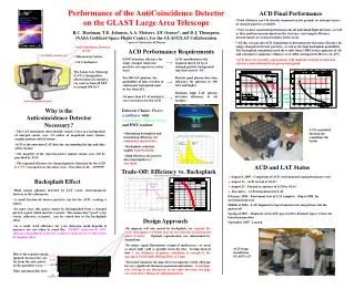
Anticoincidence Detector Overview • TILE SHELL ASSEMBLY • 89 Plastic scintillator tiles • Waveshifting fiber light collection (with clear fiber light guides for long runs) • Two sets of fibers for each tile • Tiles overlap in one dimension • 8 scintillating fiber ribbons cover gaps in other dimension (not shown) • Supported on self-standing composite shell • Covered by thermal blanket + micrometeoroid shield (not shown) • BASE ELECTRONICS ASSEMBLY • 194 photomultiplier tube sensors (2/tile) • 12 electronics boards (two sets of 6), each handling up to 18 phototubes. High voltage power supply on each board. Prototype ACD tile read out with Wavelength Shifting Fiber Tile Shell Assembly (TSA) Base Electronics Assembly (BEA)
Level III Key Requirements Summary Reference: LAT-SS-00016
ACD Subsystem 4.1.6 Dave Thompson, Subsystem Manager ACD management 4.1.6.1 Tom Johnson, Manager Deanna Adamczyk - Financial Resources Mike Walsh/Andy Eaker - Scheduling ACD Organization Chart ACD Systems Engineering 4.1.6.1.2 George Shiblie Mike Amato ACD Design and Science Support 4.1.6.1.3 Alexander Moiseev,Lead ACD Reliability and Quality Assurance 4.1.6.2 Patricia Huber, Lead Tile Shell Assembly 4.1.6.3 Ken Segal, Lead Ground Support Facilities & Equipment 4.1.6.B Jim La Ken Segal Glenn Unger Base Electronics Assembly 4.1.6.4 Glenn Unger, Lead Micrometeoroid Shield / Thermal Blanket 4.1.6.5 Ken Segal, Lead Carlton Peters, Thermal Lead Hardware Integration & Test 4.1.6.7 Jim La, Lead Mission Integration & Test Support 4.1.6.9 Bob Hartman, Lead LAT Instrument Integration & Test Support 4.1.6.8 Jim La, Lead Tile Detector Assemblies 4.1.6.3.2 A. Moiseev, Lead
ACD Team Space Flight Experience • Science • Dave Thompson - SAS-2, EGRET • Bob Hartman - SAS-2, EGRET • Alex Moiseev - GAMMA-1 • Engineering • Tom Johnson - BBXRT, COBE, EUVE, SAMPEX, TRMM, HST • George Shiblie - FUSE, MAP • Mike Amato - Spartan 201, STIS (HST), Stereo COR1 • Ken Segal - TRMM, HST, POES, EOS • Glenn Unger - MOLA, XTE, MAP • Dave Sheppard - BBXRT, XTE, TGRS, POEMS, GRS, Swift • Satpal Singh - EPACT and TGRS on WIND, Swift • Art Ruitberg - EGRET, COBE, POLAR, WIND, CASSINI, Triana • Bob Baker - HEAO, SMM, EGRET, BBXRT, XRS, XTE, Swift • Jim La - TDRS, POES, VCL/MBLA, Spartan, ROMPS, SLA, SEM • Carlton Peters - VCL, CATSAT, MAP, Triana
Summary of January Review “The Committee found that there has been significant technical progress in terms of descoping and fully optimizing the ACD, while still meeting performance requirements. A schedule and a critical path analysis needs to be done for the ACD along with a revised bottoms-up estimate of the costs. The Committee concluded that the ACD subsystem is at the PDR level but was not ready for baselining at this time.” • ACD cost estimate and schedule have been revised and integrated with the LAT PMCS. Detailed Basis of Estimate, critical path analysis and contingency analysis have been prepared. • Other (technical) recommendations from the January review are being addressed.
Status of January Review Recommendations • Finalize the design and generate the engineering drawings for the tile and fiber layout, including the lowest row of the ACD. • Designs for the 12 types of tile have been analyzed for thermal and vibration tolerances. Results are being used to generate engineering drawings. • Design for the lowest tile row is waiting for test results from two prototypes with different fiber layouts being made at Fermilab. • Preliminary drawings have been made for the routing of the fibers from the tiles to the phototubes. The routing is being checked using a mock-up of the ACD (about 80% complete). Final routing and drawings depend on the final tile designs.
Status of January Review Recommendations 2. Perform light yield tests and muon detection efficiency measurement of the final optical system (scintillator tiles; and fiber ribbons, connector, clear fibers, and photomultiplier tubes). Complete – results are similar to those shown in January: with two phototubes, 0.9997 efficiency is met; with one phototube, efficiency is ~ 0.999 Light output of Fermilab tiles is good. Light losses in the optical connector and clear fibers are higher than expected. Further tests will be done to identify and improve the light loss. LAT-TD-00843-D1, Design Qualification Tests for ACD TDA and Phototubes Performance of a full end-to-end TDA
Status of January Review Recommendations 3. Demonstrate that electronic noise of the system is low enough not to affect the muon rejection efficiency and efficiency for gammas by more than one percent. Bench tests of the first analog ASIC show no noise problem. Tests on a full electronics card are planned for October. The ACD electronics noise is required to be < 0.2 X threshold. The early calculations show that the noise at the lowest threshold setting of 0.1 MIP is approximately 50% lower than the requirement. The ACD team along with the LAT Electronics Systems Engineers have designed a grounding and shielding scheme to keep noise to a minimum.
Status of January Review Recommendations • Complete full mockup of ACD, including clear fiber layout to photomultiplier tubes. The mockup has been built and many (~80%) of the tile and fiber routing placements have been completed. Full-scale mock-up of ACD being used for tile placement and fiber routing from tiles to phototubes. Two bottom tile rows have been included. Details of mock-up.
Status of January Review Recommendations • Perform thermal cycle of fully assembled tiles and ribbons. Verify that no damage to tile/fiber assemblies takes place and light yield is not decreased. • Thermal cycle was -65 C to +45 C. • Performance was measured using a muon telescope for Minimum Ionizing Particles. • After 340 cycles, the loss of performance was less than 5%. LAT-TD-00858-D1, ACD TDA Thermal Cycling Test Light yield of Tile/fiber assembly during thermal cycling.
Status of January Review Recommendations 6. Prepare a plan for Quality Control (tile response uniformity and broken fibers) and initial calibration (ADC/minimum ionizing particle) of the ACD system prior to the delivery to the Stanford Linear Accelerator Center. • Quality Control is covered by the general ACD Quality Plan (ACD-QA-8001). Specific guidelines for handling of the TDAs will be written as an addendum to this document. • The methods for determining tile response uniformity and detecting broken fibers are documented in “Light Collection/Optical Performance Tests” (LAT-TD-00438-D2). Performance is measured using a muon telescope for Minimum Ionizing Particles. • A plan for calibrating the ACD using a muon telescope for mapping reference efficiency and then using internal triggers for PHA distributions is described in “ACD Gain Calibration Test with Cosmic Ray Muons” (LAT-TD-00844-D1). This approach was tested using the balloon flight ACD.
PAD FRAME OF TANNER I/O CELLS LVDS CELLS SIGNAL ROUTING TO PAD FRAME LOGIC CORE VDD RAIL GND RAIL Status of January Review Recommendations 7. Additional time should be added to the ASIC production schedule to provide some schedule margin. • The current LAT extended schedule incorporates an additional month for ASIC development and additional testing time. • The GSFC Program management approved qualification and screening process for the ASICs is now shorter than the original one. • The scheduled ACD completion is now 15 weeks before the LAT integration need date. GARC Layout GAFE Veto Generation – 1 MIP
Status of January Review Recommendations 8. Complete the bottoms-up Work Breakdown Structure in the Primavera framework. • The WBS has been completed and has 10 major elements: • 4.1.6.1 Project Management/Systems Engineering/Science • 4.1.6.2 Safety and Mission Assurance • 4.1.6.3 Tile Shell Assembly • 4.1.6.4 Base Electronics Assembly • 4.1.6.5 Micrometeoroid Shield/Thermal Blanket Assembly • 4.1.6.6 Mechanical Qualification and Calibration Unit • 4.1.6.7 Integration and Test • 4.1.6.8 LAT Integration and Test Support • 4.1.6.9 Mission Integration and Test Support • 4.1.6.B Ground Support Equipment and Facilities
Status of January Review Recommendations • Perform the critical path schedule analysis for the entire subsystem. Provide detailed documentation (at the lowest level of WBS) for the Basis of Estimate of the costs, in particular the on-project and off-project labor costs. One critical path has been identified (details in a later slide): • ASIC development and testing. Three iterations of the ASICs are scheduled. Turnaround time from submittal to delivery is typically at least 12 weeks. Adding testing time means that one iteration can take at least four months. Shortened time for the screening testing helps. Scheduled ACD completion is 15 weeks before the LAT integration need date. • Photomultiplier tube delivery had been a critical path. The 6-month schedule extension alleviated that pressure. A detailed Basis of Estimate is available. Summaries in later slides.
Status of January Review Recommendations • Perform the contingency analysis of the subsystem. In particular, assess contingency for the off-project labor tasks. A detailed contingency analysis, including all aspects of the ACD, has been carried out and incorporated into the PMCS. Some examples of contingency are shown in later slides.
Status of January Review Recommendations 11. Due to lack of a verifiable Work Breakdown Structure (cost estimate) for the ACD, the subsystem is not ready to be baselined at the present time. Consider the following streamlining steps: • Separate materials and services from the labor tasks at lowest WBS level • Identify all the off-project labor costs at the lowest WBS level • Use the actual, fully loaded costs for technicians, specialists, engineers, etc., in all WBS labor estimates • The PMCS contains most of this detailed information. Each resource is identified. Summaries are presented in later slides. • Because the Goddard tax system is based on estimates rather than actuals, the labor costs are not fully loaded. • Conduct a Subsystem Baseline Review as soon as the work on the subsystem Work Breakdown Structure is completed. This is that review.
ACD Work Flow Overview Tile Detector Assemblies 09/03 Tile Shell Assembly 11/03 Shell 03/03Subassembly ASIC 09/03 Development Front End Electronics Card Assembly 12/03 High Voltage Bias Supply 08/03 Base Electronics Assembly 01/04 ACD Performance and Environmental Test 5/04 ACD Integration 02/04 Photomultiplier tubes 10/03 Ship 06/04 Base Frame 02/03 Subassembly Thermal Blanket Micrometeoroid Shield 08/03 Completion Dates Shown
Goddard Costing • Labor • Civil Service - We do not pay salary for Civil Servants, but we do pay Multi-Program Support (MPS, see below) • Contractor - We pay contractor costs plus MPS • Taxes • MPS - This tax pays for Goddard overhead and is charged for flight projects at a flat rate of $35K per on-site FTE, based on the estimated manpower usage. • Lab Tax - This tax pays for local services such as computer systems support, publications, and office supplies. It is charged at a rate of 4% of the total cost of the project. • Procurements • Ordinary - Purchase Requests are issued. Large items are required to be competed unless justified as sole source. • Shop - Fabrication purchases made through the Goddard shops may be done in-house or sent to contractors. Costs are estimated by Goddard staff, but they get bids to determine actual cost.
Cost/Manpower Overview by Fiscal Year FTE 1976 hours
Cost/Manpower Overview by Task Civil Service personnel salaries are paid by Goddard, not the LAT. Taxes: Goddard overhead, charged on the basis of on-site FTE and total cost.
Summary • The ACD continues to make technical progress. Most of the technical recommendations from the January review have been resolved. Additional test planning is still needed. • The ACD has developed a coherent, verifiable cost and schedule plan. Basis of Estimate, critical path analysis and contingency have been clarified. • The schedule has three months of float at the end. • The ACD faces no unusual risks. The risks are those experienced by any space flight instrument.
Second Quarter FY03 Cost Spike • Costs show a peak in FY03 Q 2 – total of $1.5 M • Manpower is about the same as other Q 0.3 M • Extra MPS and lab taxes are costed this Q 0.5 M • Several major hardware purchases this Q • Flight TDAs 0.2 M • Flight fiber cables 0.1 M • PMT housing assembly 0.1 M • Mechanical GSE 0.09 M • Thermal Vac cables 0.085 M
ACD Technical Heritage • Plastic Scintillator - used in all previous gamma-ray telescopes OSO-3, SAS-2, COS-B, CGRO (all 4 instruments), plus many cosmic ray experiments. • Waveshifting fibers - used in GLAST LAT Balloon Flight Engineering Model (BFEM). Waveshifting bars used by HEXTE on RXTE (same material in a different geometry) • Photomultiplier tubes - used in all previous gamma-ray telescopes. HEXTE/RXTE used a commercial version of the same tube we are using (Hamamatsu 4443), and GOLF on SOHO used the same tube as the ACD except for the cathode material (Hamamatsu 4444) • High Voltage Bias Supplies - used in all previous gamma-ray telescopes, plus many cosmic ray experiments. • Electronics - similar ASIC’s (same designer) used on the BFEM. Discriminators, PHA and logic signals similar to many flight instruments. • Micrometeoroid Shield - Improved version (more layers, stronger materials) of shield that protected EGRET successfully for nine years.
Meeting the Level III Key Requirements Backsplash Loss <20% at 300 GeV Detection Efficiency 0.9997 Black line: measured efficiency Green line: efficiency with 15% loss Blue line: efficiency with 40% loss Measurements at SLAC and CERN
Light Absorption in Fibers – an Issue Absorption in the waveshifting fibers is substantial. Absorption in the clear fibers is not negligible, and appears higher than advertised by the vendor.
ACD Optimization - Summary • Light Collection - optimized with 5 mm fiber spacing, TETRATEC wrapping material, aluminized fiber ends, multiclad fibers. Scintillator manufacturer does not matter. Two sets of interleaved fibers for redundant readout. • Absolute Efficiency - using the light collection described above, a single phototube meets the 0.9997 efficiency requirement at 0.3 MIP threshold if there are no appreciable light losses. With two tubes operating, there is ample margin. Light losses in long waveshifting fibers or connector to clear fibers makes the single tube marginal. • Broken Fibers - the ACD could meet its requirements with up to two broken fibers on up to three tiles. • Segmentation - the 89-tile design meets the backsplash requirements. • Hermeticity - a double layer of square 1.5 mm fibers with offset centers provides adequate sealing of the gaps between tiles. • REFERENCE: LAT-TD-00438-D2
End-to-end efficiency and light yield measurement Tested detectors: Sample 1. 32cm by 32 cm tile with two (short) bundles of WSF fibers - flight prototype Sample 2. similar tile, but with fiber-to-fiber optical connector and 115 cm long clear fiber bundles Sample 3. similar tile, but with thermally spliced 65 cm long clear fibers Tests were performed with cosmic muons according to the scheme shown in Fig.1 (M1, M2, S1, S2, S3 - triggering detectors, T1 and T2 - tiles being tested)